Template:Peculiar Features of Modbus Controllers
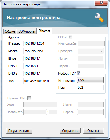
To stat work with the Insyte controller via the Modbus TCP protocol activate the possibility of work via this protocol in the Ethernet tab of the controller network settings. Example of configuration:
Register addresses of the Insyte controller start with 1. In the standard realization of the Modbus (TCP) protocol and in iRidium they start with 0. It should be taken into account - move the address by "-1" in relation to Insyte when creating a command for controlling registers.
For reference to Insyte VARIABLES use the following formula:
Address = 1000 + [slot number]*2
Every variable has the slot number. It is seen when you point the cursor on the variable. The Type: Holding Register and Word Size: Dword(32-bit) data types are used for sending commands to variables.
For sending IR commands via Insyte:
Address = the address of the IR emitter the commands are sent from
The number of the IR command is set up as the Value (number) property when dragging the command on a graphic item. The command is assigned to the item with the Send Number event.
Address = 16384 + 12 - 1 = 16395
(value 16384 is defined by the Beckhoff structure, 12 – the variable index, 1 – considers the beginning of countdown with 0)
When setting up the controller it is required to add the ТСР Port of connection to the controller in the FIX property. It is 502 by default.
One port supports one connection of the TСР Master (iRidium client)
Numbers of Modbus registers can be seen by addresses with the type %QB7.1.5.
The last number minus one – it is the register address which will be indicated in iRidium:
Address = %QB7.1.5 - 1 = 5 - 1 = 4
