EPSNET: Examples of Controlling Registers
PLC with EPSNET support have several memory areas available for data writing and reading. These areas can contain any information. That is why the instructions contain several particular examples for controlling variables of memory registers. Controlling variables of any type can be performed by the principles described in the examples below.
Contents
Rules of Addressing for EPSNET Registers in iRidium
Export the controller configuration in the SCADA format to get the list of addresses and bits in the addresses you need to add in iRidium for controlling one or another controller input/output.
Export of addresses is available in Mosaic (TECO) and IDM (iNELS).
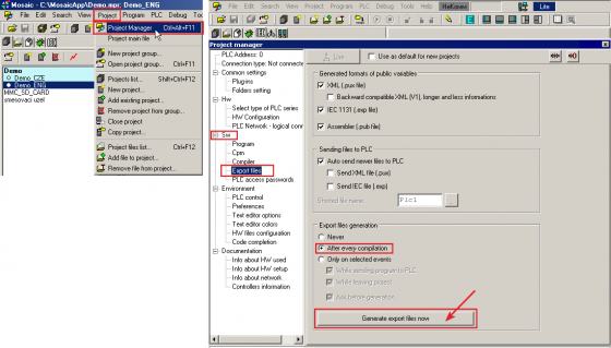
Setting up export in Mosaic:
Important: if you already generated the *.pub file (compiled the project), before doing it again delete the previous *.pub file, otherwise addresses in the project will be duplicated.
Setting up export in IDM iNELS:
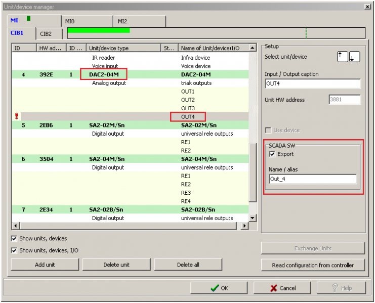
Select variables for export in the managing program of the device: "Unit/Device Manager". Do not forget to indicate the NAMES of the exported variables:
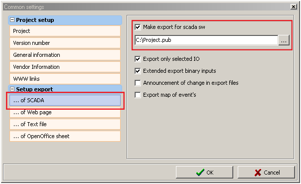
Open "Project Setup" and indicate the path for saving the export file. The tab can be called '...Of SCADA' or 'RELI':
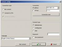
For the *.pub file to be exported on PC you need to upload the configuration on the controller:
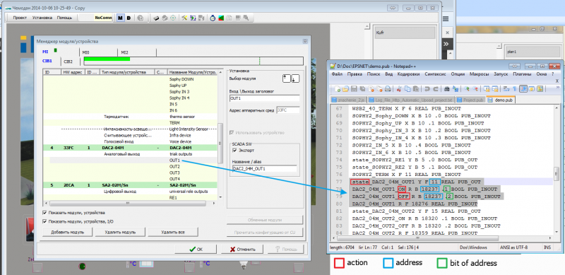
You can open the *.pub file in the text editor. It contains the list of addresses in the iRidium supported format. For example:
Address parameters:
state_DAC2_04M_OUT1 Y F 11 REAL PUB_OUT
DAC2_04M_OUT1_ON R B 18237 .1 BOOL PUB_INOUT
DAC2_04M_OUT1_OFF R B 18237 .2 BOOL PUB_INOUT
DAC2_04M_OUT1 R F 18276 REAL PUB_INOUT
state_DAC2_04M_OUT1 Y F 11 REAL PUB_OUT
- state_NAME – the address for reading the register state
- Y – the register type (Register: Y)
- F - the register size (Type: Float...)
- 11 – the register address (Address: 11)
- _OUT = Read Only
DAC2_04M_OUT1_ON R B 18237 .1 BOOL PUB_INOUT
- NAME_ON – the address for channel activation (ON only)
- R – the register type (Register: R)
- B - the register size (Type: Bool)
- 18237 - the register address (Address: 18237)
- .1 - the bit address in the address (Bit: 1)
- _INOUT = Read/Write
Usually bits are presented as follows: 0 = ON, 1 = OFF, 2 = TRIG
DAC2_04M_OUT1 R F 18276 REAL PUB_INOUT
- NAME – the address for dimming (controlling the range)
- R - the register type (Register: R)
- F - the register size (Type: Float...)
- 18276 - the register address (Address: 18276)
- _INOUT = Read/Write
Controlling Boolean Values
To control logic variables (in particular, for switching separate bits) it is necessary to create commands (Command) and feedback channels (Feedback) in the project device tree in iRidium. Commands are required for sending data, feedback channels are required for reading the current variable status.
For registers available for reading only it is possible to display the current state.
Setting up commands in iRidium GUI Editor:
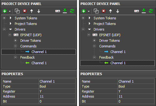
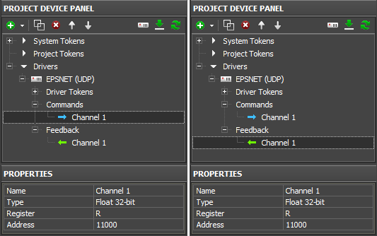
To control boolean variables (taking values 0 or 1) create a command for setting up the state and a feedback channel for displaying its actual status:
Properties for setting up:
Name: the register name, at random
Type: the variable size
Register: variable
Address: the byte address
Bit: the bit number in the byte (0..7)
When the command and feedback channel are ready (they form the pair which helps to control the register state) you should set up graphic items. Switching 2 possible states (0/1) of the boolean variable is possible with the help of the following graphic items:
- Button – when assigning the command to Button indicate the number which should be sent to the variable at each pressing. This value cannot be changed when working with the project.
- Trigger Button is used for switching two preset values, for example 100% and 0% of brightness. The values are indicated when setting up the graphic item. Trigger Button defines the value for sending at the next pressing depending on the current value received with the help of the feedback channel.
Setting up Values by Button
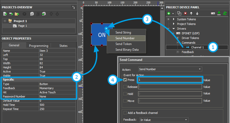
Create and set up the graphic item - Button – for sending 0 or 1 value to the variable. Assign the command to Button following the steps below:
1. Setting up of the register variable is performed according to the first section of the instructions.
2. Setting up of the graphic item is performed in the Object Properties: General tab.
Select Type: Button and set up the item:
- Feedback – the way of reacting on events:
- Momentary – for Button which goes to the active state at pressing on it and returns to the initial state at releasing it
- Channel – for Button which should receive feedback from the variable and go the active state when receiving value 1 from it.
Other properties should be set if it is required.
3. Assigning of the command to the graphic item should be made with the "Send Number" tag in the dialog window - the number which you will indicate in the dialog window will be sent.
4. Selecting of the event and value for sending is done depending on the required behavior of the item. If Button should send a number at pressing on it select the Press event and the required number. If Button should switch the variable only at pressing indicate Press: 1, Release: 0.
- You can activate "Add a Feedback Channel" to assign the feedback channel with the same name as command automatically. If you want to assign the feedback channel later use the "In Value" tag to affect the item state.
Trigger Switching
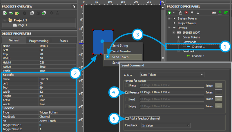
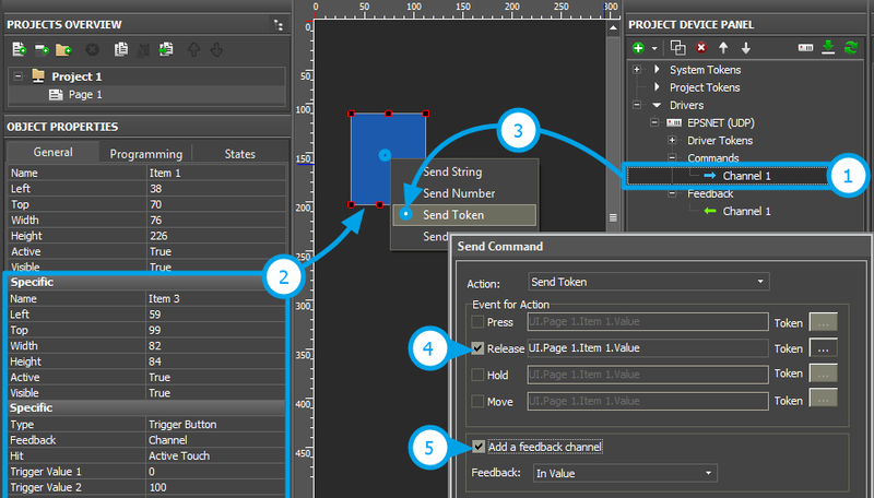
Trigger Button is used for switching two selected values of the variable. They are 0 and 1 for logic variables. Set up Trigger Button and assign the register to it following the steps below:
1. Setting up of the register is performed according to the first section of the instructions. For Trigger Button it is required to have the command and feedback channel. Trigger Button will not work correctly without the feedback channel.
2. Setting up of the graphic item is performed in the Object Properties: General tab.
Select Type: Trigger Button and set up the item:
- Feedback – the way of reacting on events:
- Channel – the item should process data received from the equipment and display them.
- Trigger Value 1 and Trigger Value 2 – values the item switches at each pressing (0/1). Every time the item selects the value opposite to the current one for sending. The feedback channel is used for receiving the current value.
- Other properties should be set if it is required.
3. Assigning of the command to the graphic item should be made with the "Send Token" tag in the dialog window - the item will send the value opposite to the current Value at pressing.
4. Selecting the event of command sending – Press or Release.
5. Activating of "Add a Feedback Channel" is required to assign the feedback channel with the same name as command automatically. It fastens work with the device tree. If you want to assign the feedback channel later use the "In Value" tag to affect the item state.
Controlling the Range
The dimming function is typical for controlling light, temperature, etc. It can be used for controlling signed and unsigned variables, numbers with floating point. You can set up dimming of any controller variable in iRidium. In order to do that you need to create a command (Command) and a feedback channel (Feedback) in the project device tree. Commands are required for sending data; feedback channels are required for reading the current variable status.
For variables available for reading only dimming is impossible but it is possible to display the current state on a slider or screen.
Setting up commands in iRidium GUI Editor:
For the variable which change in the preset range (for example it can be a dimmer for light) create a command for setting up the state and a feedback channel for displaying its actual status:
Properties for setting up:
Name: the register name, at random
Type: the variable size
Register: variable
Address: the byte address
When the command and feedback channel are ready (they form the pair which helps to control the register state) you should set up graphic items. Dimming, increment/decrement and switching of the register states can be done with the help of the following graphic items:
- Level is used for regulating the value in the preset range by moving the Level slider. It can be used for controlling the variable or for displaying its status.
- Trigger Button is used for switching two preset values, for example 100% and 0% of brightness. The values are indicated when setting up the graphic item. Trigger Button defines the value for sending at the next pressing depending on the current value received with the help of the feedback channel.
- Up/Down Button is used for incrementing/decrementing the current variable value received from the feedback channel.
Dimming by Level
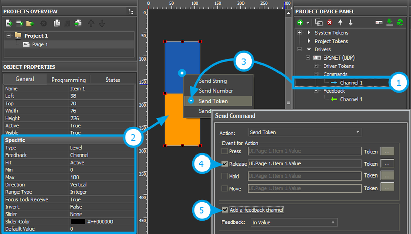
Create and set up the graphic item - Level – for controlling the controller variable. Assign the command to the item following the steps below:
1. Setting up of the variable is performed according to the first section of the instructions. For dimming it is required to have the command and feedback channel. Level will not display the actual state without the feedback channel.
2. Setting up of the graphic item is performed in the Object Properties: General tab.
Select Type: Level and set up the item:
- Feedback – the way of reacting on events:
- Channel – for Level which will monitor the actual variable status
- Momentary - for Level which will NOT display the actual variable status
- Min: 0 – the lowest value of the Level scale
- Max: 100 - the highest value of the Level scale
- The Min...Max range defines the limits of regulation. By reducing the limits you can create a cutoff (the regulation range which is less than the available one).
- Direction: Vertical/Horizontal – the item position
Other properties should be set if it is required.
3. Assigning of the command to the graphic item should be made with the "Send Token" tag in the dialog window - the item will send the value selected at the moment by the slider (Token: Value of the graphic item).
4. Selecting the event of command sending can be done at random, but it is better to use the combination of Press and Release (the first is sent when touching Level, the second – when releasing it). The Move event will send values with the moving slider; but it can overload the controller (use with caution).
5. Activating of "Add a Feedback Channel" is required to assign the feedback channel with the same name as command automatically. If you want to assign the feedback channel later use the "In Value" tag to affect the position of the Level slider.
Increment/Decrement
It is convenient to use Up/Down Buttons for accurate regulation (for example, +\- 1°C). Set them up in the iRidium project:
Indicate the following in the settings of Up/Down Buttons:
- Feedback – the way of reacting on events:
- Momentary – the item should react on pressings (this feedback type is recommended)
- Up/Down Value – the step of increment/decrement at each pressing ("-10" / "10" – decrement or increment)
- Min/Max Value – limits which cannot be exceeded. For decrementing indicate the lowest regulation value, for incrementing – the highest (for example, "0" for the decrementing step "-10", and "100" for incrementing step "10").
Assignment of the command and feedback channel is performed as for Level. The items will not work correctly without the feedback channel.
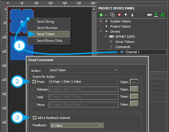
1. Assigning of the command to the graphic item should be made with the "Send Token" tag in the dialog window - the item will send the value which is lower or higher than the current one.
2. Selecting the event of command sending - Press or Release.
3. Activating of "Add a Feedback Channel" is required to assign the feedback channel with the same name as command automatically. If you want to assign the feedback channel later use the "In Value" tag to affect the current item state.
Trigger Switching
Trigger Button is used for switching two selected values of the variable. Set up Trigger Button and assign the register to it following the steps below:
1. Setting up of the register is performed according to the first section of the instructions. For Trigger Button it is required to have the command and feedback channel. Trigger Button will not work correctly without the feedback channel.
2. Setting up of the graphic item is performed in the Object Properties: General tab.
Select Type: Trigger Button and set up the item:
- Feedback – the way of reacting on events:
- Channel – the item should take the state corresponding to the current variable value.
- Trigger Value 1 and Trigger Value 2 – values the item switches at each pressing. Every time the item selects the value opposite to the current one for sending. The feedback channel is used for receiving the current value.
- Other properties should be set if it is required.
3. Assigning of the command to the graphic item should be made with the "Send Token" tag in the dialog window - the item will send the value opposite to the current Value at pressing.
4. Selecting the event of command sending – Press or Release.
5. Activating of "Add a Feedback Channel" is required to assign the feedback channel with the same name as command automatically. It fastens work with the device tree. If you want to assign the feedback channel later use the "In Value" tag to affect the item state.
Setting up Values by Button
Create and set up the graphic item - Button – for sending a number to the variable. The number should be in the available range of the selected variable (it depends on the variable size). Assign the command to Button following the steps below:
1. Setting up of the register variable is performed according to the first section of the instructions.
2. Setting up of the graphic item is performed in the Object Properties: General tab.
Select Type: Button and set up the item:
- Feedback – the way of reacting on events:
- Momentary – for Button which goes to the active state at pressing on it and returns to the initial state at releasing it
- Channel – for Button which should receive feedback from the variable and go the active state when receiving value 1 from it.
Other properties should be set if it is required.
3. Assigning of the command to the graphic item should be made with the "Send Number" tag in the dialog window - the number which you will indicate in the dialog window will be sent.
4. Selecting of the event and value for sending is done depending on the required behavior of the item. If Button should send a number at pressing on it select the Press event and the required number. If Button should switch the variable only at pressing indicate Press: 1, Release: 0.
- You can activate "Add a Feedback Channel" to assign the feedback channel with the same name as command automatically. If you want to assign the feedback channel later use the "In Value" tag to affect the item state.
Displaying the Status
The current state of the controller variable can be displayed on the selected item of the graphic interface. It is convenient to use Buttons, Levels, Display Buttons (Buttons with 1 state).
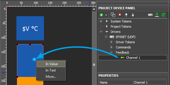
The feedback channel can be assigned to the graphic item with the "In Text" or "In Value" tag depending on what graphic item property the value from the channel will affect:
- In Value – the value received from the feedback channel. It will change the graphic item state switching it from the non-active to active or moving the Level slider. «Templates of value output on items» (see below) are also used at work.
- In Text – the value received from the feedback channel will substitute any text which was written in the graphic item text field by default.
- More... – here you can select any graphic item property the value from the channel should affect, for example, opacity, activity or X and Y coordinates.
Templates of processing and outputting data for feedback channels:
Template |
Function |
Template |
Function |
$P |
Output of the current level value in percentage | $V |
Output of the current value |
$L |
Output of the lower level value | $H |
Output of the upper level value |
$S |
Output of the current state number | $A |
Output of the current value minus the lower level value |
$R |
Output of the level range (Upper level value minus lower level value) | $F1-5 |
Output of the value with a floating point, number of symbols after a point |
$X |
Output of the current value in the hex type | $$ |
Output of the "dollar" symbol |
A command (template) of incoming data processing and displaying is entered into the text field of a graphic item and can be combined with other text or symbols (comments, units of measurement)
