Examples of Communication with Joins of Crestron Equipment
Contents
- 1 Send the Values 1 or 0 (Buttons On and Off) to Digital Joins
- 2 Triggers for Switching Digital Joins
- 3 Display the Digital Join value by Changing the Item State
- 4 Send Values from Buttons to Analog Joins
- 5 Send Values from Levels to Analog Joins
- 6 Send Values from Up/Down Buttons to Analog Joins
- 7 Display Numeric Values of Analog Joins on Items
- 8 Display Values of Analog Joins on Uncontrolled Levels
- 9 Receive Data Strings (Serial) form the Controller and Display them on Items
Send the Values 1 or 0 (Buttons On and Off) to Digital Joins
To set the value of the Digital type join (the bit data type) to 1 or 0 you can use Button sending the corresponding values to the join with the help of a command. Setting up the sending of values 1 or 0 to Digital joins:
- 1. Create a command for referring to the join (Command Join):

|
| ||||||||
- 2. Create and set up two Buttons (for sending 1 or 0 to the join, on/off):
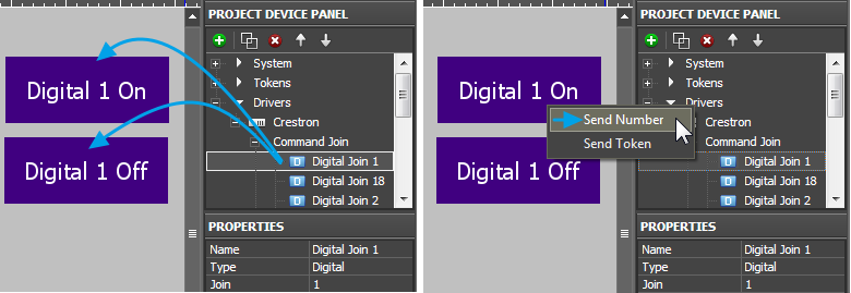
- 3. Bind the command to the items indicating its data type and outgoing value:
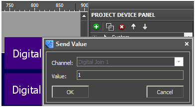
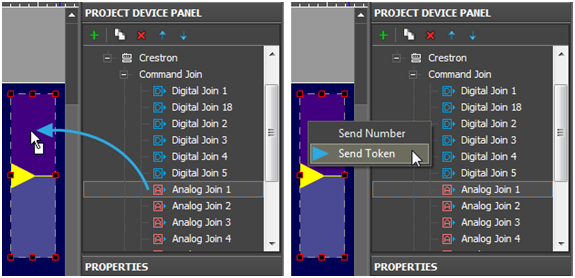
To send values to the controller select Send Number – send numbers in the decimal format. This data type is used when it is required to send fixed values. After selecting ”Send Number” the window(input field) is opened where you are required to write the number sent to the join at pressing on the graphic item:
The Digital (the bit type) channel can take values 1 or 0. When binding the command to the graphic item indicate 1 or 0.
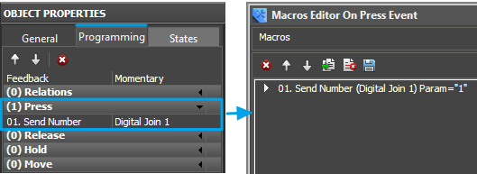
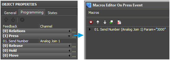
The command bound to the item is displayed in the Programming tab:
By default the command is bound to the Press event (pressing on the item) but it can be changed by dragging to another event (Release, Hold or Move). In the window for forming macros you can set up other commands which can be performed on the preset event. The list of supported commands is available in the macros window.
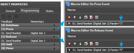
The command can be bound to several graphic items (like Buttons On = 1 and Off = 0 for the Crestron join), or it can be bound to the same item with different values and to different events. For example, to send 1 when pressing on the item and 0 when releasing the item:
Triggers for Switching Digital Joins
Digital type joins can take values 0 or 1. In some cases it is more convenient to set this values from one button (not from different items) working as a trigger – i.e. the item changes the join state to the opposite at each pressing. Setting up Digital joins for switching values 1 and 0:
- 1. Create a command for referring to the join (Command Join):
| |||||||||
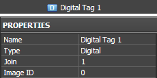
- 2. Create a channel of the join status (Feedback Join) for correct operation of the trigger:
|
| ||||||||||
- 3. Create and set up Trigger Button (for switching join values between 1 and 0):

| ||||||||||||||
|
- 4. Bind the command for the join to Trigger Button:
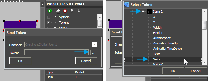
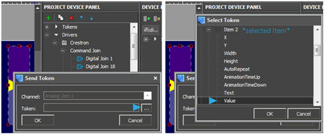
To send data select Send Token – send values taken by one of the graphic item properties to the bus. In this case it is Value – the current state of the graphic item. For Trigger Button the value of the Value property is defined by Trigger Value 1 and Trigger Value 2 and also by the current join value.
- 5. When selecting the property which affects the outgoing value indicate Value of the Trigger Button item:
If the current join value equals to Trigger Value 1 then at pressing on the item the opposite value i.e Value 2 will be sent and vice versa.
- 6. Bind the join status channel to Trigger Button:
The join status channel bound InValue forms the current value of Valuefor the graphic item. Value is used by Trigger Button for sending values to the join. It is required to have the channel reading the join current state when working with Trigger Button. The command and status channel bound to the item are displayed in the Programming tab of the item settings:
Display the Digital Join value by Changing the Item State
To receive the current status of the Digital join which can take values 1 or 0 and then display it on a graphic item you need to use the join status channel and the graphic item – Button with 2 states. When receiving 0 from the join status channel, Button takes State 1; when receiving 1,it takes State 2.
- 1. Create a channel for receiving the join status (Feedback Join):

|
| ||||||||||
- 2. Create and set up Button with 2 states which is going to display the join status.
Button with Feedback: Channel does not react on pressings but changes its state when the value in the join bound to it changes.

| |||||||||||||||
| |||||||||||||||
- 3. Bind the status channel to Button:
The join status channel bound InValue forms the current item, i.e when Value changes the item states also changes and that helps to visualize the change of the join status. The command and status channel bound to the item are displayed in the Programming tab of the item settings:
Send Values from Buttons to Analog Joins
To send values to the Analog (unsigned 16-bit)type join use Button sending the command of setting the preset join value. Sending values is performed in the way similar to Digital joins but the available ranges are different.
- 1. Create a command for referring to the join:

|
| ||||||||
- 2. Create and set up Button for sending values to the join:

| |||||||||||||||
| |||||||||||||||
- 3. Bind the command to the item indicating the outgoing value:
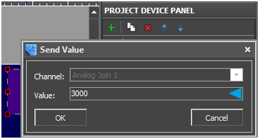
To send values to the controller select Send Number – send a number in the decimal format. After selecting Send Number the window (input field) is opened where you are required to write the value sent to the join at pressing on the graphic item:
The Analog (unsigned 16-bit) channel can take values in the range from 0 to 65535. When binding the command to the graphic item indicate the outgoing value (for example, 3000). The command bound to the item is displayed in the Programming tab:
By default the command is bound to the Press event (pressing on the item) but it can be changed by dragging it to another event (Release, Hold or Move). In the window for forming macros you can set up other commands which can be performed on the preset event. The list of supported commands is available in the macros window.
Send Values from Levels to Analog Joins
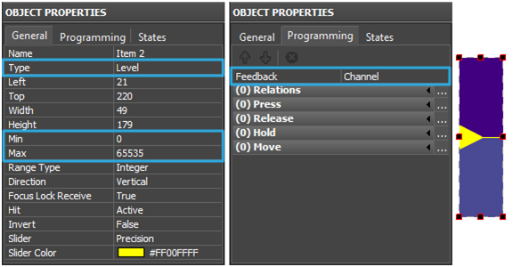
To send values to the Analog (unsigned 16-bit) type join it is convenient to use the Level type item. You can send any value from the preset Level range by moving the Level slider.
- 1. Create a command for referring to the join:

|
| ||||||||
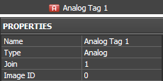
- 2. Create a join status channel for initial actuation of the Level state at the project launch and displaying the actual join value:
|
| ||||||||||
- 3. Create and set up Level for sending values to the join:
| |||||||||||||||||
| |||||||||||||||||
- 4. Bind the command to the item indicating the outgoing value:
To send values to the controller select Send Token – send the value which the Level Value property is going to take i.e. the position of the slider. After selecting Send Token the window is opened where you are required to choose the property to be sent to the join:
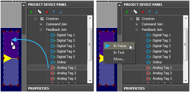
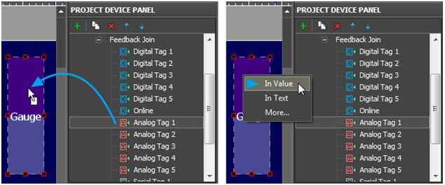
Bind the status channel to the item so the Level could always display the join actual value. After moving the slider it is fixed in the new position when the actual join value is changed.
The join status channel bound In Value forms the current item state i.e. when Value changes the position of the Level slider also changes. It enables the visualization of the join status change at the project launch and having accurate data about the current join status.
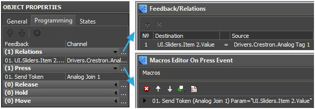
The commands and channels bound to the item are displayed in the Programming tab of the item:
Send Values from Up/Down Buttons to Analog Joins
One of the ways for controlling the join value and the most convenient one when controlling temperature or other values with the preset step of change is using the Up/Down Button item type.
- 1. Create a command for controlling the join and a channel for receiving its status (Feedback Join).
The status channel is required in this case. Without the status channel (information about the current join value) Up/Down Button does not work.

|

|
Settings of the channel and command are the same as when working with Level.
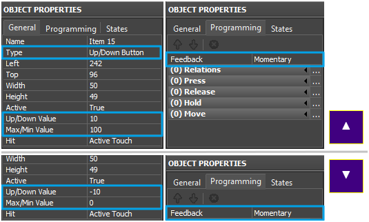
- 2. Create graphic items – Up Button and Down Button:
| |||||||||||||||||||
| |||||||||||||||||||
- 3. Bind the command and the join channel to the items:
Bind the command as Send Token as the value sent to the join is formed from the properties of the graphic item (Up/Down Value and Min/Max Value) depending on the current variable value (Value):
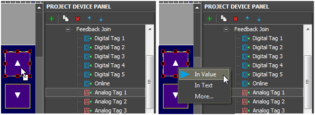
The join status channel is bound In Value for forming the current value of the Up/Down Button item which is used when forming the value outgoing to the join:
The commands and channels bound to the item are displayed in the Programming tab:
Display Numeric Values of Analog Joins on Items
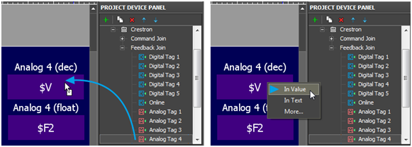
To receive the current Analog join status and then display it on a graphic item use the join status channel and Button with 1 state and special text template which enables you to output values on the item in the required format.
- 1. Create a join status channel (Feedback Join)

|
| ||||||||||
- 2. Create and set up Button with 1 state to display the join status:
Button with Feedback: Channel does not react on pressings but changes the value in the text field when the value in the join bound to it changes. Also the item state changes if there are more states than one.

| |||||||||||||||||
| |||||||||||||||||
In the text field of the item (the States tab, the Text menu entry) the following templates of value output on items, which convert data received from the join, are used:
Template |
Function |
Template |
Function |
$P |
Output of the current level value in percentage | $V |
Output of the current value |
$L |
Output of the lower level value | $H |
Output of the upper level value |
$S |
Output of the current state number | $A |
Output of the current value minus the lower level value |
$R |
Output of the level range (Upper level value minus lower level value) | $F1-5 |
Output of the value with a floating point, number of symbols after a point |
$X |
Output of the current value in the hex type | $$ |
Output of the "dollar" symbol |
A command (template) of incoming data processing and displaying is entered into the text field of a graphic item and can be combined with other text or symbols (comments, units of measurement)
- 3. Bind the status channel to Button
The join status channel bound InValue forms the current item state. The number in the DEC, HEX or Float format is formed and output as text on the item on the basis of the item Value by the template of value output which is indicated in the text field.
The status channel bound to the item is displayed in the Programming tab of the item:
Display Values of Analog Joins on Uncontrolled Levels
To display the value received from the join by the slider position of Level created for outputting data in the preset range it is required to:
- 1. Create a channel for receiving the join status (Feedback Join)

|
| ||||||||||
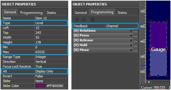
- 2. Create and set up Level to display the join status:
| |||||||||||||||||||||
| |||||||||||||||||||||
In the text field of the item (the States tab, the Text menu entry) the following templates of value output on items, which convert data received from the join, are used:
Template |
Function |
Template |
Function |
$P |
Output of the current level value in percentage | $V |
Output of the current value |
$L |
Output of the lower level value | $H |
Output of the upper level value |
$S |
Output of the current state number | $A |
Output of the current value minus the lower level value |
$R |
Output of the level range (Upper level value minus lower level value) | $F1-5 |
Output of the value with a floating point, number of symbols after a point |
$X |
Output of the current value in the hex type | $$ |
Output of the "dollar" symbol |
A command (template) of incoming data processing and displaying is entered into the text field of a graphic item and can be combined with other text or symbols (comments, units of measurement)
- 3. Bind the status channel to Level:
The join status channel bound In Value forms the current item state. The slider moves depending on the current Value. The item ignores external events as it has a property not to react on pressings.
Receive Data Strings (Serial) form the Controller and Display them on Items
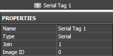
To receive data in the ASCII format (any data string) from the controller use the Serial data type. This type is used only in channels for reading data from the controller. It is not possible to send a string to the controller directly from iRidium App. To actuate the string stored in the controller use an Analog or Digital join.
To receive data strings from the controller and output them on graphic items it is required to:
- 1. Create a channel for receiving the join status (Feedback Join)
|
| ||||||||||
- 2. Create a graphic item where the received data string is going to be displayed on
Such graphic item usually has only 1 state as it does not react on pressings and outputs received data in the text field only.

| |||||||||||||||
| |||||||||||||||
- 3. Bind the channel for receiving data to the graphic item:
The channel is bound In Text for writing the data string received from the controller directly in the item text. Templates of value output are not used for writing strings.

