Examples of Communication with Modbus Variables
Contents
Writing Data in Coil Registers
Coil Register – flag registers containing 1-bit values. Coil Registers are available for reading and writing data.
To send data to Coil Registers use commands (Commands) create on the output of the Modbus driver. Initiation of commands is performed by graphic items the commands are assigned to. Data received from the controller can affect properties of graphic items including values which sending is initiated by the item. Some types of graphic items use both the value writing channel and the channel reading the variable state for work (Trigger Button, Up/Down Button).
The following graphic items can be used for controlling Coil Registers of the Modbus driver:
- Button – sending fixed values to the register (0 or 1); displaying the register state by changing the Button state or outputting the register value on the item as text.
- Trigger Button – switching two states of the Coil Register (0 and 1). It is required to have a channel reading the current state of the controlled register for work of Trigger Button. Depending on the current state the item selects the value which will be sent to the controller when pressing on the item (0 or 1).
Writing Values in Coil by Button
1. Create a command for sending values to the Coil Register
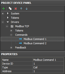
The command is created in the Project Device tree and it is set up for working with the selected register type:
| Name | a command name (at random) |
| Device ID | an address of the dependent device/controller (Slave ID) |
| Type | a type of the register the command refers to (Coil Register) |
| Address | an address of the controlled Coil Register |
2. Create a graphic item – Button – for sending values to the register
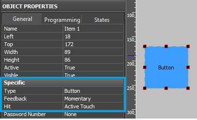
The item will initiate value sending to the register. The value is indicated when dragging the command on the graphic item. To select the fixed value indicate the "Send Number" event when assigning the command.
| Type | a graphic item type - Button. Button is used for sending fixed values in the register. |
| Feedback | an item feedback type - Momentary. The item will change its state when pressing on it but the data received from the controller will not affect its state. |
| Hit | item reaction on pressings - Active Touch. All non-transparent part of the graphic item will be active for pressings. |
3. Assign the command to the graphic item
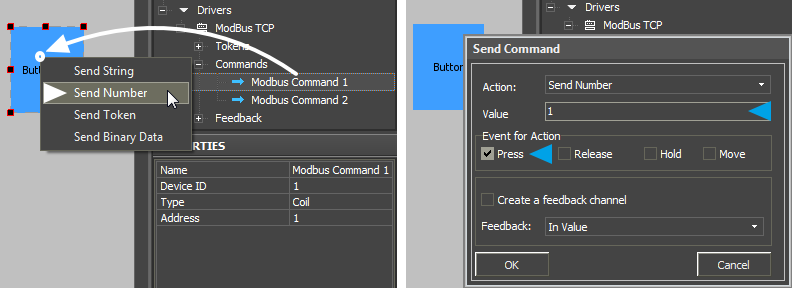
Assigning of the command is performed by the Drag&Drop method - dragging. In the process of assigning indicate the type of outgoing data and the event the data will be sent to the controller:
| Drop-down list which appears when dragging the command on the item: | |
| Send Number | send a fixed whole number in the decimal format to the register. The value is indicated in the dialog window. The Send Number event is always used when working with Buttons. |
| Dialog window of the Send Number event: | |
| Value | the field for inputting values (whole decimal numbers) which will be sent to the register. It is always 0 or 1 for Coil Registers. |
| Event for Action | the event the indicated Value will be sent to the register at (Press – when pressing on the item, Release – when releasing the item; other events are not used for Button) |
When you performed all the actions above you can launch Emulation of project work. When having a license iRidium Emulator will connect to the controlled controller and at each pressing on the set up Button it will send 1 to the Coil Register with the address indicated in settings.
You can also set up sending of 0 to the register (for example for separate ON and OFF items).
Writing Values in Coil by Trigger Button
1. Create a command for sending values to the Coil Register
The command is created in the Project Device tree and it is set up for working with the selected register type:
| Name | a command name (at random) |
| Device ID | an address of the dependent device/controller (Slave ID) |
| Type | a type of the register the command refers to (Coil Register) |
| Address | an address of the controlled Coil Register |
2. Create a graphic item – Trigger Button – for switching the register state
At each pressing the item will initiate switching between two states of the Coil Register (0 and 1). It is required to have a channel reading the current state of the controlled register for work of Trigger Button. Depending on the current state the item selects the value which will be sent to the controller when pressing on the item (0 or 1). Also the channel reading the current state of the register is required to initiate the work of Trigger button at the project launch.
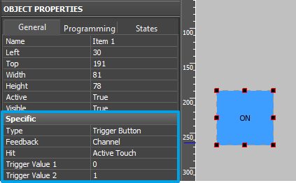
| Type | a graphic item type - Trigger Button. It is used for switching the register to the state opposite to the current one. |
| Feedback | an item feedback type - Channel. The item will change its state depending on the actual current value of the controlled register. It is required for initiation of Trigger Button work and correct displaying of its current state (with the help of the channel reading the register state) |
| Hit | item reaction on pressings - Active Touch. All non-transparent part of the graphic item will be active for pressings. |
| Trigger Value 1 Trigger Value 2 |
two possible states of Trigger Button (usually active and inactive). It is always 0 and 1 for Coil Registers. 1 corresponds to the second (active) state of Trigger Button. |
| * States | for proper work trigger Button should always have 2 states (State 1 and State 2) which are set up in the States tab of graphic item properties. |
3. Assign the command to the graphic item
Assigning of the command is performed by the Drag&Drop method - dragging. In the process of assigning indicate the type of outgoing data and the event the data will be sent to the controller:
| Drop-down list which appears when dragging the command on the item: | |
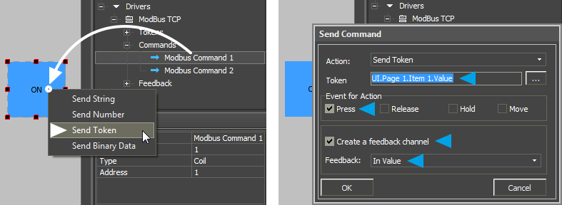
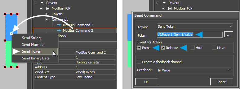
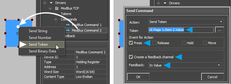
| Send Token | the command for sending one of the possible values of Trigger Button (Trigger Value 1 and Trigger Value 2) to the register. The current state of Trigger Button is defined by the item Value property. On the basis of this value the trigger forms the value for sending to the register. The Send Token event is selected when the item should send the variable (not a fixed number) which depends on the user actions and the item state. So Send Token is always used when working with Levels, Trigger Buttons and Up/Down Buttons. |
| Dialog window of the Send Token event: | |
| Token | the Value property defines the current state of Trigger Button (Trigger Value 1 or Trigger Value 2), that is why when selecting the source of the outgoing value indicate Value of the item. This property will be selected in the dialog window by default; leave it as it is and go to the next setting. |
| Event for Action | the event the indicated Value will be sent to the register at (Press – when pressing on the item, Release – when releasing the item; other events are not used for Trigger Button) |
| Create a feedback channel | the command for creating the channel for receiving the register status automatically. The channel is created in the basis of the command assigned to the item; it has the same name and properties. Creation of the feedback channel (using the “Create a feedback channel” tool or manual creation) is required when working with Trigger Button. Without this channel the trigger will not know the current register state and will be unable to select the value opposite to the current one. |
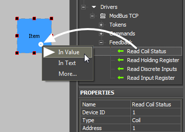
| Feedback: In Value |
this setting defines the item property the created channel for reading the status will affect. For Trigger Button the received value should affect item Value (state) so we select the In Value event. |
When you performed all the actions above you can launch Emulation of project work. When having a license iRidium Emulator will connect to the controlled controller and at each pressing on the set up Trigger Button it will read the current state of the controlled Coil Register. On the basis of the current register state the trigger selects and sends the value opposite to the current one to the register.
Trigger Button is a convenient tool for substituting the separate items to control Coil Registers one of which sets up the value to 1, the other to 0.
Writing Data in Holding Registers
Holding Registers – registers containing (in the standard Modbus protocol) 16-bit values. Holding Registers are available both for reading and writing data.
To send data to Holding Registers use commands (Commands) create on the output of the Modbus driver. Initiation of commands is performed by graphic items the commands are assigned to. Data received from the controller can affect properties of graphic items including values which sending is initiated by the item. Some types of graphic items use both the value writing channel and the channel reading the variable state for work (Trigger Button, Up/Down Button, Level).
The following graphic items can be used for controlling Holding Registers of the Modbus driver:
- Button – sending fixed values to the register (in the range of 16-bit - signed or unsigned values); displaying the register state by outputting the current register value in the item text field.
- Level – setting up variable values in the range defined by the Level limits; outputting the received register value on Level
- Trigger Button – switching two random states of the Holding Register (for example, 0 and 65535). Depending on the current state the item selects the value which will be sent to the controller when pressing on the item (0 or 65535).
- Up/Down Button – implement or decrement of the current register value by the preset value from the current one. Limits and a increment/decrement step are indicated at the item setting.
Writing Values in Holding Registers by Button
1. Create a command for sending values to the Holding Register
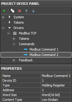
The command is created in the Project Device tree and it is set up for working with the selected register type:
| Name | a command name (at random) |
| Device ID | an address of the dependent device/controller (Slave ID) |
| Type | a type of the register the command refers to (Holding Register) |
| Address | an address of the controlled Holding Register |
| Word Size | word size of the Holding Register. Word (16-bit) – for the standard Modbus protocol |
| Content Type | sequence of writing register bytes. Low Endian – for the standard Modbus protocol |
2. Create a graphic item – Button – for sending values to the register
The item will initiate value sending to the register. The value is indicated when dragging the command on the graphic item. To select the fixed value indicate the "Send Number" event when assigning the command.
| Type | a graphic item type - Button. Button is used for sending fixed values in the register. |
| Feedback | an item feedback type - Momentary. The item will change its state when pressing on it but the data received from the controller will not affect its state. |
| Hit | item reaction on pressings - Active Touch. All non-transparent part of the graphic item will be active for pressings. |
3. Assign the command to the graphic item
Assigning of the command is performed by the Drag&Drop method - dragging. In the process of assigning indicate the type of outgoing data and the event the data will be sent to the controller:
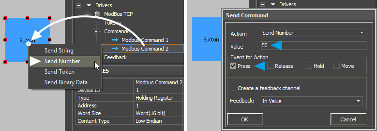
| Drop-down list which appears when dragging the command on the item: | |
| Send Number | send a fixed whole number in the decimal format to the register. The value is indicated in the dialog window. The Send Number event is always used when working with Buttons. |
| Dialog window of the Send Number event: | |
| Value | the field for inputting values (whole decimal numbers) which will be sent to the register. For Holding Registers – it is any number in the range of 16 bit. |
| Event for Action | the event the indicated Value will be sent to the register at (Press – when pressing on the item, Release – when releasing the item; other events are not used for Button) |
When you performed all the actions above you can launch Emulation of project work. When having a license iRidium Emulator will connect to the controlled controller and at each pressing on the set up Button it will send the value to the Holding Register with the address indicated in settings.
Writing Values in Holding Registers by Level
1. Create a command for sending values to the Holding Register
The command is created in the Project Device tree and it is set up for working with the selected register type:
| Name | a command name (at random) |
| Device ID | an address of the dependent device/controller (Slave ID) |
| Type | a type of the register the command refers to (Holding Register) |
| Address | an address of the controlled Holding Register |
| Word Size | word size of the Holding Register. Word (16-bit) – for the standard Modbus protocol |
| Content Type | sequence of writing register bytes. Low Endian – for the standard Modbus protocol |
2. Create a graphic item – Level – for controlling the value
When pressing on a Level zone the register will receive the value corresponding to the zone. Limits of regulation are indicated at Level setting up. The item should always have 2 states. It can work both with and without the feedback channel.
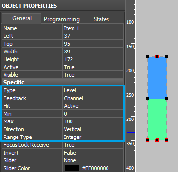
| Type | a graphic item type - Level. It is used for setting up the register value in the preset range. |
| Feedback | an item feedback type - Channel. Level will take the indicated value at pressing but when receiving data about changing the register value from the controller the slider will take the new position. |
| Hit | item reaction on pressings - Active Touch. All non-transparent part of the graphic item will be active for pressings. |
| Min Max |
minimum and maximum Level values it can take |
| Direction | Level orientation – horizontal or vertical |
| Range Type | a data type Level operates with. Integer – whole numbers, Float – numbers with floating point |
| * States | for proper work Level should always have 2 states (State 1 and State 2) which are set up in the States tab of graphic item properties. |
3. Assign the command to the graphic item
Assigning of the command is performed by the Drag&Drop method - dragging. In the process of assigning indicate the type of outgoing data and the event the data will be sent to the controller:
| Drop-down list which appears when dragging the command on the item: | |
| Send Token | the command for sending one of the available Level values to the register. The current Level state is defined by the item Value property. The ‘‘Send Token event is selected when the item should send the variable (not a fixed number) which depends on the user actions and the item state. So Send Token is always used when working with Levels, Trigger Buttons and Up/Down Buttons. |
| Dialog window of the Send Token event: | |
| Token | the Value property defines the current position of the Level slider, that is why when selecting the source of the outgoing value indicate Value of the item. This property will be selected in the dialog window by default; leave it as it is and go to the next setting. |
| Event for Action | the event the indicated Value will be sent to the register at (Press – when pressing on the item, Release – when releasing the item, Move – when moving the Level slider all intermediate values taken by it will be sent until the item is released). It is recommended to assign the command to 2 events at one time - Press and Release – when working with Level. The Move event can create unnecessary load of the controller due to the big amount of transferred data. |
When you performed all the actions above you can launch Emulation of project work. When having a license iRidium Emulator will connect to the controlled controller and at each pressing on the set up Level it will send the value corresponding to the selected Level zone to the register with the address indicated in settings.
Writing Values in Holding Registers by Trigger Button
1. Create a command for sending values to the Holding Register
The command is created in the Project Device tree and it is set up for working with the selected register type:
| Name | a command name (at random) |
| Device ID | an address of the dependent device/controller (Slave ID) |
| Type | a type of the register the command refers to (Holding Register) |
| Address | an address of the controlled Holding Register |
| Word Size | word size of the Holding Register. Word (16-bit) – for the standard Modbus protocol |
| Content Type | sequence of writing register bytes. Low Endian – for the standard Modbus protocol |
2. Create a graphic item – Trigger Button – for switching the register state
At each pressing the item will initiate switching between two states of the Holding Register (for example, 0 and 65535). Depending on the current state the trigger selects the value which will be sent to the controller when pressing on the item. Also the channel reading the current state of the register is required to initiate the work of Trigger Button at the project launch.
| Type | a graphic item type - Trigger Button. It is used for switching the register to the state opposite to the current one. |
| Feedback | an item feedback type - Channel. The item will change its state depending on the actual current value of the controlled register. It is required for initiation of Trigger Button work and correct displaying of its current state (with the help of the channel reading the register state) |
| Hit | item reaction on pressings - Active Touch. All non-transparent part of the graphic item will be active for pressings. |
| Trigger Value 1 Trigger Value 2 |
two possible states of Trigger Button (usually active and inactive). For Holding Registers it can be any 2 values in the 16-bit range. |
| * States | for proper work Trigger Button should always have 2 states (State 1 and State 2) which are set up in the States tab of graphic item properties. |
- if the actual value in the register does not match to any of the two indicated values, at the next pressing on Trigger Button the register will receive the value indicated in the Trigger Value 2 field
3. Assign the command to the graphic item
Assigning of the command is performed by the Drag&Drop method - dragging. In the process of assigning indicate the type of outgoing data and the event the data will be sent to the controller:
| Drop-down list which appears when dragging the command on the item: | |
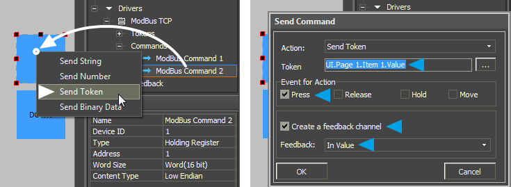
| Send Token | the command for sending oe of the possible values of Trigger Button (Trigger Value 1 and Trigger Value 2) to the register. The current state of Trigger Button is defined by the item Value property. On the basis of this value the trigger forms the value for sending to the register. The Send Token event is selected when the item should send the variable (not a fixed number) which depends on the user actions and the item state. So Send Token is always used when working with Levels, Trigger Buttons and Up/Down Buttons. |
| Dialog window of the Send Token event: | |
| Token | the Value property defines the current state of Trigger Button (Trigger Value 1 or Trigger Value 2), that is why when selecting the source of the outgoing value indicate Value of the item. This property will be selected in the dialog window by default; leave it as it is and go to the next setting. |
| Event for Action | the event the indicated Value will be sent to the register at (Press – when pressing on the item, Release – when releasing the item; other events are not used for Trigger Button) |
| Create a feedback channel | the command for creating the channel for receiving the register status automatically. The channel is created in the basis of the command assigned to the item; it has the same name and properties. Creation of the feedback channel (using the “Create a feedback channel” tool or manual creation) is required when working with Trigger Button. Without this channel the trigger will not know the current register state and will be unable to select the value opposite to the current one. |
| Feedback: In Value |
this setting defines the item property the created channel for reading the status will affect. For Trigger Button the received value should affect item Value (state) so we select the In Value event. |
When you performed all the actions above you can launch Emulation of project work. When having a license iRidium Emulator will connect to the controlled controller and at each pressing on the set up Trigger Button it will read the current state of the controlled Holding Register. On the basis of the current register state the trigger selects and sends the value opposite to the current one to the register.
Writing Values in Holding Registers by Up/Down Button
1. Create a command for sending values to the Holding Register
The command is created in the Project Device tree and it is set up for working with the selected register type:
| Name | a command name (at random) |
| Device ID | an address of the dependent device/controller (Slave ID) |
| Type | a type of the register the command refers to (Holding Register) |
| Address | an address of the controlled Holding Register |
| Word Size | word size of the Holding Register. Word (16-bit) – for the standard Modbus protocol |
| Content Type | sequence of writing register bytes. Low Endian – for the standard Modbus protocol |
2. Create a graphic item - Up/Down Button
At each pressing the item will refer to the controlled register, read its current value and after adding the preset value to the current one send the data to the register as a new value. It is used for precise regulation of temperature or other data relative to the current value. The channel reading the current register state is required to work with Up/Down Button.
| Type | a graphic item type - Up/Down Button. It is used for precise regulation of temperature or other data relative to the current value. |
| Feedback | an item feedback type - Momentary. The item will change its state when pressing on it for visual fixation; the feedback type does not affect calculation of the incremented/decremented value |
| Hit | item reaction on pressings - Active Touch. All non-transparent part of the graphic item will be active for pressings. |
| Up/Down Value | the value you need to increment/decrement the current value of the controlled register (whole numbers); it can be positive ("1") or negative ("-1") |
| Min/Max Value | limits of increment/decrement, values which cannot be exceeded. For increment (Up/Down Value > 0) – indicate the upper limit, for decrement (Up/Down Value < 0) – indicate the lower limit. |
3. Assign the command to the graphic item
Assigning of the command is performed by the Drag&Drop method - dragging. In the process of assigning indicate the type of outgoing data and the event the data will be sent to the controller:
| Drop-down list which appears when dragging the command on the item:' | |
| Send Token | the command for sending incremented/decremented values to the register. The current state of Up/Down Button is defined by the item Value property. On the basis of this value the item forms the incremented/decremented value for sending to the register. The Send Token event is selected when the item should send the variable (not a fixed number) which depends on the user actions and the item state. So Send Token is always used when working with Levels, Trigger Buttons and Up/Down Buttons. |
| Dialog window of the Send Token event: | |
| Token | the Value property stores the current value and forms a new incremented/decremented value for sending that is why when selecting the source of the outgoing value indicate Value of the item. This property will be selected in the dialog window by default; leave it as it is and go to the next setting. |
| Event for Action | the event the indicated Value will be sent to the register at (Press – when pressing on the item, Release – when releasing the item; other events are not used for Up/Down Button) |
| Create a feedback channel | the command for creating the channel for receiving the register status automatically. The channel is created in the basis of the command assigned to the item; it has the same name and properties. Creation of the feedback channel (using the “Create a feedback channel” tool or manual creation) is required when working with Up/Down Button. Without this channel Up/Down Button will not know the current register for forming and sending incremented/decremented values. |
| Feedback: In Value |
this setting defines the item property the created channel for reading the status will affect. For Up/Down Button the received value should affect item Value (state) so we select the In Value event. |
When you performed all the actions above you can launch Emulation of project work. When having a license iRidium Emulator will connect to the controlled controller and at each pressing on the set up Up/Down Button it will read the current state of the controlled Holding Register. On the basis of the current register state Up/Down Button selects and sends the incremented/decremented values to the register.
Reading Data about the State of Registers
In accordance with the standards of the Modbus protocol, iRidium can refer to the following register types Type for receiving data:
- Coil Register – 1-bit, reading and writing data
- Holding Register – 16-bit word, reading and writing data
- Discreet Inputs - 1-bit, reading data only
- Input Register - 16-bit word, reading data only
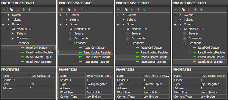
To receive data about states of registers iRidium uses feedback channels (Feedbacks) where the properties of the register which status you need to receive are indicated. The channels are created in the Feedbacks tab of the Modbus driver in the project device tree.
The driver receives data about the state of variables on the basis of the list of channels it has. Displaying of the received data received is performed with the help of graphic items the commands are assigned to. The data received from the controller can be displayed in the text field of the item or they can affect the item current state.
Setting up Channels for Receiving Data about the State of Registers
iRidium can receive data about the state of 4 register types: Coil Register, Holding Register, Discreet Inputs, Input Register. All these register types are set up in the project device tree. The channel properties look as follows:
| Name | a channel name (at random) |
| Device ID | an address of the dependent device/controller (Slave ID) |
| Type | a type of the register the command refers to (Holding Register) |
| Address | an address of the controlled Holding Register |
| Word Size | word size of the Holding Register. Word (16-bit) – for the standard Modbus protocol |
| Content Type | sequence of writing register bytes. Low Endian – for the standard Modbus protocol |
The created channels can affect various properties of graphic items – states, appearance and activity. They can display data about the current register state in the item text field.
To assign a channel to a graphic item use the Drag&Drop method. While assigning the channel indicate the item property the selected channel will affect:
The most frequently used ways of channels affecting graphic items:
- In Value – the channel affects the Value property – the graphic item state. When he register goes to any non-zero value if it is Button the graphic item will change its state to the active one (from State 1 to State 2); if it is Level the item will change the slider position.
Also In Value is used for working with complex graphic items - Trigger Button, Up/Down Button and participates in calculating the values these items need to send to the register.
In Value is used when working with templates for processing the ingoing data and displaying them on the item ($V, $P, $F1, ...)
- In Text – the channel writes the value received from the register in the item text field substituting the text in it. The absolute value without conversion is written there. That is why this type is NOT used when working templates for processing the ingoing data and displaying them on the item.
- More... – when it is necessary you can set up more complex ways of the channel affecting the graphic item properties. For example, the register value can change coordinates or item opacity level, it can make it inactive for pressings or invisible.
Changing the Item State When Changing the Register Value
In order to change the item state when changing the register state it is required to assign the channel of the register status to the graphic item using the In Value function – i.e. create the connection so the channel could affect the Value property (state, value) of the graphic item.
Application:
- changing the Button or Multistate Button state when receiving the zero value from the register of any type
- changing the slider position of Level or Multistate Level when receiving values from Holding or Input Registers (in the 16-bit range)
- working with Trigger Button and Up/Down Button which require channels of receiving the register status.
Settings of graphic items for displaying the register status:
1. Button changing its state when the register takes any non-zero value:
| Type | a graphic item type – Button with 2 states |
| Feedback | an item feedback type. Always use Channel to display the received register status. |
| Hit | item reaction on pressings. If the item only displays the variable status and does not have to send commands select Pass Through. If the item has to send commands and receive data select Active Touch. |
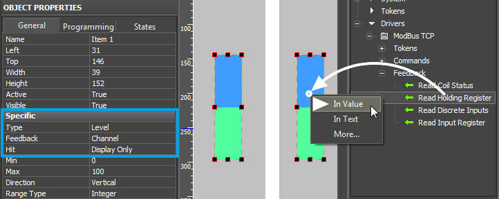
2. Level changing the slider position when changing the register value:
Level is used for working with registers the status of which can change in the wide range and that is why it is suitable for the status of Holding or Input Register (16 or 32-bit range).
| Type | a graphic item type – Level |
| Feedback | an item feedback type. Always use Channel to display the received register status. |
| Hit | item reaction on pressings. If the item only displays the variable status and does not have to send commands select Display Only. If the item has to send commands and receive data select Active.
. |
3. The feedback channel is required for assigning to Trigger Button and Up/Down Button along with the command of setting up the register value. The command and channels have to have the same settings (refer to the same register) for correct work of these items.
Displaying the Current Register Value in the Item Text Field
Application (output of the value received from the channel in text is possible in the following two ways):
- Displaying of the absolute value received by the channel from the register in the item text field
- Receiving and displaying the state of any register in the item text field when the value has to be previously converted by one of the templates for processing and displaying of ingoing data ($V, $P, $F1, ...)
Settings of graphic items:
1. Output the register value in the item text field without any conversion
In order to output the data in the text field (with substitution of the data there) use the "In Text" command when dragging the channel to the graphic item. It can be used for any type of graphic items; it substitutes item text in all its states.
| Type | a graphic item type – Button or any other item |
| Feedback | an item feedback type. It does not affect the outputting values in the item text field so you can indicate any feedback type. |
| Hit | item reaction on pressings. If the item only displays the variable status and does not have to send commands select Pass Through. If the item has to send commands and receive data select Active Touch. |
2. Display data using templates for processing of values and outputting them in the item text
It is the item with a template for processing and outputting the value on the graphic items in its text field. The template processes the value received from the register and outputs them in the required formatпреобразующий полученное значение регистра в нужный формат:
Template |
Function |
Template |
Function |
$P |
Output of the current level value in percentage | $V |
Output of the current value |
$L |
Output of the lower level value | $H |
Output of the upper level value |
$S |
Output of the current state number | $A |
Output of the current value minus the lower level value |
$R |
Output of the level range (Upper level value minus lower level value) | $F1-5 |
Output of the value with a floating point, number of symbols after a point |
$X |
Output of the current value in the hex type | $$ |
Output of the "dollar" symbol |
A command (template) of incoming data processing and displaying is entered into the text field of a graphic item and can be combined with other text or symbols (comments, units of measurement)
| Type | a graphic item type - Button with one state (State 1) |
| Feedback | an item feedback type. The template ($V, $P, $S, ...) work does not depend on the feedback type. You can indicate any feedback type depending on the properties of the item you use the template with. |
| Hit | item reaction on pressings. If the item only displays the variable status and does not have to send commands select Pass Through. If the item has to send commands and receive data select Active Touch. |
Peculiar Features of Modbus Controllers
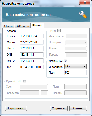
To stat work with the Insyte controller via the Modbus TCP protocol activate the possibility of work via this protocol in the Ethernet tab of the controller network settings. Example of configuration:
Register addresses of the Insyte controller start with 1. In the standard realization of the Modbus (TCP) protocol and in iRidium they start with 0. It should be taken into account - move the address by "-1" in relation to Insyte when creating a command for controlling registers.
For reference to Insyte VARIABLES use the following formula:
Address = 1000 + [slot number]*2
Every variable has the slot number. It is seen when you point the cursor on the variable. The Type: Holding Register and Word Size: Dword(32-bit) data types are used for sending commands to variables.
For sending IR commands via Insyte:
Address = the address of the IR emitter the commands are sent from
The number of the IR command is set up as the Value (number) property when dragging the command on a graphic item. The command is assigned to the item with the Send Number event.
Address = 16384 + 12 - 1 = 16395
(value 16384 is defined by the Beckhoff structure, 12 – the variable index, 1 – considers the beginning of countdown with 0)
When setting up the controller it is required to add the ТСР Port of connection to the controller in the FIX property. It is 502 by default.
One port supports one connection of the TСР Master (iRidium client)
Numbers of Modbus registers can be seen by addresses with the type %QB7.1.5.
The last number minus one – it is the register address which will be indicated in iRidium:
Address = %QB7.1.5 - 1 = 5 - 1 = 4
Controlling RGB LED Lighting with Color Picker
Control of RGB LED lighting (DMX controller) is performed with the help of special module. It converts a color selected from the palette to commands. The commands set up values in three Holding registers of Modbus corresponding to the preset values of red, blue and green color of the LED strip light.
Value for the register controlling the brightness of the LED strip light is sent separately – with the help of Level (not written in script). You can use any type palette as Color Picker.
Creating graphic items for controlling RGB by LED strip light:
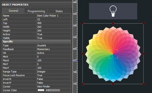
- 1. Color Picker – the palette for color selection
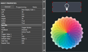
Color Picker – a graphic item with the type "Joystick". In the Image field of the item you should indicate the color palette. The joystick defines the color which should be separated into the colors of the RGB palette under the cursor. At that the joystick cursor can be transparent.
It is important to indicate the range from 0 to 100 for Х and Y coordinates. The settings should be as indicated as for an image.
- 2. The item for displaying the color and controlling the brightness
Trigger Button with two states which will switch the LED strip light on/off and display the color under the Color Picker cursor if the LED strip light is activated.
Forming the list of commands for controlling the LED strip light
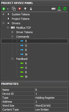
Create 4 group addresses for controlling "Type: Holding" in the Modbus device tree.
The commands should be related to the numbers of registers regulating the colors of the LED strip light (R, G, B) and its brightness (RGB Brightness).
Adding the script for controlling Color Picker in your project
The script for controlling Color Picker should be copied in the Script Editor window of GUI Editor or import it there as a *.js file.
When creating a new script indicate its name (it should not have numbers only) and add the code for the Color Picker module control:
function work_pick_color(in_color_picker, in_color_resipient, in_sRed, in_sGreen, in_sBlue)
{
   var device = IR.GetDevice("Modbus TCP");                        // Modbus TCP Driver in your Project Device Tree
   var color = in_color_picker.PickColor;
   var red = (color  >> 24) & 0xFF;
   var green = (color >> 16) & 0xFF;
   var blue = (color >> 8) & 0xFF;

   in_color_resipient.GetState(1).FillColor = color;

   device.Set(in_sRed, red);
   device.Set(in_sGreen, green);
   device.Set(in_sBlue, blue);
}

//Processing module of DMX 1. Copy the module to control one more ColourPicker:

IR.AddListener(IR.EVENT_ITEM_RELEASE,
               IR.GetItem("ColorPicker").GetItem("Item Color Picker 1"),        //  Color Picker (Page.Item)
               function()
               {
                  work_pick_color(
                     IR.GetItem("ColorPicker").GetItem("Item Color Picker 1"),  //  Color Picker (Page.Item)
                     IR.GetItem("ColorPicker").GetItem("Item Display Color 1"), //  Display Colour Item (Page.Item)
                     "R",                                                       //  Red Channel
                     "G",                                                       //  Green Channel
                     "B");                                                      //  Blue Channel
               }
               );
Download the file of the Modbus Color Picker script
In the script settings (in the lines with the corresponding comments) indicate the following:
- the name of the Modbus driver in the project tree
- Color Picker - the name of the page and RGB pallete item on this page
- Display – the name of the button for displaying the color and controlling the brightness
- Red, Green, Blue - the names of the channels in the Modbus project tree where the corresponding colors in the range from 0 to 255.
Assigning the command regulating the brightness of the LED strip light to the graphic item – Trigger Button. The command is assigned when selecting the "Press" interface event. Also mark "Add a Feedback Channel" in the same dialogue window.
After that the module is fully ready for work.
Download the example of the module for controlling the LED strip light RGB (Modbus)
