Basic Operation of iRidium with Modbus Controllers
Contents
- 1 Principles of Communication of iRidium Control Panels with Modbus
- 2 Setting Up the Connection to the Modbus-compatible Controller
- 3 Switching Between the Local and Internet Connection
- 4 Features of Particular Controllers
- 5 Import of Modbus Commands and Channels
- 6 Sending Commands and Reading Data by the Modbus protocol
- 7 Emulation of Project Work
- 8 Launching Projects on Control Panels
Principles of Communication of iRidium Control Panels with Modbus
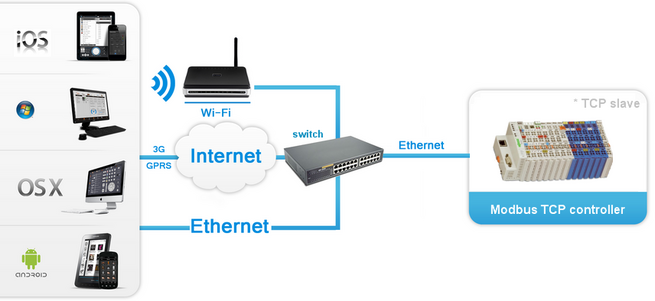
Technology of connecting iRidium App to the controller via Modbus TCP suggests using the client-server model where iRidium App is the main (Master) device which initiates transactions to the dependent (Slave) controller. You do not need any additional hardware to work with the controller via Modbus TCP as iRidium connects to the controller directly.
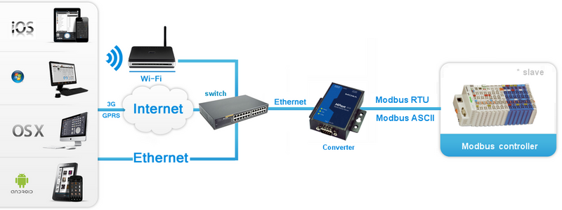
When connecting iRidium App to the controller via Modbus RTU or ASCII the same model of data transfer is used but it is required to have a converter from TCP to Modbus RTU/ASCII. You can use any gateway available on the Automation Market as such converter.
When using the converter from TCP to Modbus RTU or ASCII it is required to use the corresponding driver (Modbus TCP to RTU, Modbus TCP to ASCII) in iRidium GUI Editor.
Setting Up the Connection to the Modbus-compatible Controller
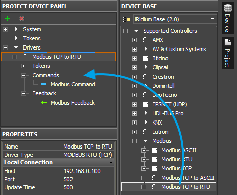
For setting up connection to the Modbus-compatible controller you are required to create a device defining the way and properties of communication with the Modbus controller in GUI Editor. iRidium data base for Modbus contain the following driver templates:
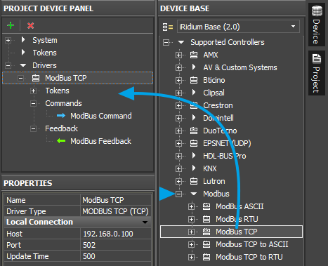
- Modbus TCP – the driver for direct connection to the controller via Modbus TCP without any additional hardware or software. iRidium uses TCP/IP connection for communicating with the controller.
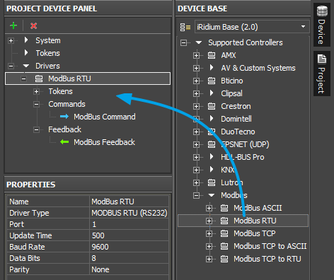
- Modbus RTU and ‘‘‘Modbus ASCII – the drivers for connection to the controller via Modbus RTU and ASCII using RS232/RS485 serial networks. When using these protocols the iRidium application can be launched only on the device physically connected to the controller by the serial port of data transfer.
- Modbus TCP to RTU and Modbus TCP to ASCII – the drivers for connection to the controllers which can be operated only via Modbus RTU and Modbus ASCII when the connection to them is performed through a special format converter (not directly). The converter receives commands TCP/IP (through the Ethernet port) and sends commands to the controller in the Modbus RTU or Modbus ASCII formats (see Scheme 2 in the previous section of the present article).
Below you can find examples of setting connection to the controller in iRidium GUI Editor:
Connection to the Controller via Modbus TCP
For connection to the compatible controller via Modbus TCP create a new iRidium project and add there Modbus TCP driver from iRidium data base. After that it is required to set up properties of connection to the controller using TCP/IP connection. For that it is necessary to indicate the controller IP-address (private or public), the TCP port for connection to the controller and connection properties:
| Host | an IP-address of the controller |
| Port | a TCP port for connection to the controller (by default - 502) |
| Update Time (мс) | frequency of transactions (frequency of sending requests about change of status of controller variables). When working in the local network the recommended values are 500...1000 ms (1000...1500 мс – when working via the Internet). |
For working with the controller via the Internet indicate the public IP-address of the router the controller is connected to in the connection settings. Port Forwarding Service is set up for the router to enable remote control – referring to the local (private) address of the controlled controller from the Internet.
You can learn the external (public) IP-address of your router with the help of external resources, for example [1]
Connection to the Controller via Modbus RTU or ASCII
For connection to the compatible controller via Modbus RTU or ASCII without using converters (i.e. through RS232/RS485 serial networks) create a new iRidium project and add there Modbus RTU (ASCII) driver from iRidium data base. After that it is required to set up properties of connection to the Com-port for sending data to the controller. The requirement of direct connection to the controller Com-port makes it possible to install iRidium projects only on the PC which is physically connected to the controller through the COM-port:
| Port | a number of the СОМ-port the controller is connected to |
| Update Time (мс) | frequency of transactions (frequency of sending requests about change of status of controller variables). The recommended values are 1000...2000 мс |
| Baud Rate | speed of exchanging data with the controller |
| Data Bits | a number of data bits in a frame |
| Parity | parity checking |
| The stop bit in a frame is always 1 | |
Connection to the Controller via Modbus RTU or ASCII through ТСР/IP Gateway
Connection to the compatible converter via Modbus RTU (ASCII) using a converter from TCP/IP to Modbus RTU (ASCII) defines the way of storing Modbus RTU (ASCII) commands in the format suitable for transferring data via IP and their further converting by the converter to the initial format. Special derivers - Modbus TCP to RTU and Modbus TCP to ASCII - in iRidium data base serve for such data converting. In this case communication with the controller is performed according to the Scheme 2 described in the first section.
Create a new iRidium project and add there Modbus TCP to RTU (TCP to ASCII) driver from iRidium data base. After that it is required to set up properties of connection to the converter TCP/IP to Modbus RTU (TCP to ASCII) via IP:
| Host | an IP-address of the converter |
| Port | a TCP port for connection to the converter |
| Update Time (мс) | frequency of transactions (frequency of sending requests about change of status of controller variables). When working in the local network the recommended values are 500...1000 ms (1000...1500 мс – when working via the Internet). |
For working via the Internet indicate the public IP-address of the router the converter TCP/IP to Modbus RTU (TCP to ASCII) is connected to. Port Forwarding Service is set up for the router to enable remote control – referring to the local (private) address of the controlled controller from the Internet.
You can learn the external (public) IP-address of your router with the help of external resources, for example [2]
Switching Between the Local and Internet Connection
If the control panel should hold the connection with the system when the panel is out of the limits of the Wi-Fi network of the system, you need to set up the switch between the Internet and the local network.
The remote mode suggests connection to the system via the Internet. At that the external IP-address or the domain name of the system to which you need to connect have to be used.
 In iRidium Wi-Fi/3G CANNOT be switched automatically. For switching between the Internet and the local network you need buttons with special settings. See the settings below.
 To control the system remotely you have to open the system for external access -
to set up the Port Forwarding Service.
 To secure equipment from unauthorized access we recommend using secure connection with the remote system (VPN).
Setting up of the switch Wi-Fi/3G in iRidium projects:
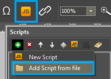
1. Open the script editor in iRidium GUI Editor.
2. Download and add into your project the template of the Wi-Fi/3G switch (Add Script from file):
download the template of the Wi-Fi/3G switch
The Wi-Fi/3G switch is performed with the help of the script function SetParameters
Setting up of parameters of the Wi-Fi/3G switch:
- function Internal_1() // Function name
- {
- IR.GetDevice('ModBus TCP').SetParameters({Host: '192.168.0.66', Port: '502', UpdateTime: '1000'}); // Driver Name + Parameters
- }
- function External_1()
- {
- IR.GetDevice('ModBus TCP').SetParameters({Host: '220.115.10.10', Port: '502', UpdateTime: '1000'});
- }
Indicate in the command settings:
- Function name – the name of the switch function (command). Two functions cannot have the same name in a project.
- Driver Name – the name of the driver which parameters are changed
- Parameters – the set of the switch parameters which you need to apply to the driver
Assign commands to buttons:
- Select the button which will be responsible for the Wi-Fi/3G switch.
Open the properties of the button: Object Properties > Programming - Open Macros Editor of the button for the Press or Release events
- Select the Script Call command and add it by double-clicking on it
- Select the name of the function you want to activate in the drop-down list. Create the command.
Set up access to the equipment from the Internet:
In order to do that open the equipment ports for remote access.
Download the example of the Wi-Fi/3G switch (project) >>
Features of Particular Controllers
Characteristic features of addressing characteristic for different Modbus-compatible controllers
Beckhoff
Beckhoff CX8090. Modbus/ADS memory card:
| Modbus areas | Modbus address (HEX) | Modbus address (DEC) | ADS area | |
|---|---|---|---|---|
| Digital inputs | 0x0000 - 0x7FFF | 0 - 32767 | Index group: 0xF021 - process image of physical inputs (bit access) |
Index offset: 0x0 |
| 0x8000 - 0x80FF | 32768 - 33023 | Name of the variables in PLC program: .mb_Input_Coils |
Data type: ARRAY [0..255] OF BOOL | |
| Digital outputs (coils) | 0x0000 - 0x7FFF | 0 - 32767 | Index group: 0xF031 - process image of physical outputs (bit access) |
Index offset: 0x0 |
| 0x8000 - 0x80FF | 32768 - 33023 | Name of the variables in PLC program: .mb_Output_Coils |
Data type: ARRAY [0..255] OF BOOL | |
| Input registers | 0x0000 - 0x7FFF | 0 - 32767 | Index group: 0xF020 - process image of physical inputs |
Index offset: 0x0 |
| 0x8000 - 0x80FF | 32768 - 33023 | Name of the variables in PLC program: .mb_Input_Registers |
Data type: ARRAY [0..255] OF WORD | |
| Output registers | 0x0000 - 0x2FFF | 0 - 12287 | Index group: 0xF030 - process image of physical outputs |
Index offset: 0x0 |
| 0x3000 - 0x5FFF | 12288 - 24575 | 0x4020 - PLC memory area | 0x0 | |
| 0x6000 - 0x7FFF | 24576 - 32767 | 0x4040 - PLC data area | 0x0 | |
| 0x8000 - 0x80FF | 32768 - 33023 | Name of the variables in PLC program: .mb_Output_Registers |
Data type: ARRAY [0..255] OF WORD | |
Read/Write Holding Registers.
- iPad1 AT %MB0 : WORD; (*адрес 12288*)
- iPad2 AT %MB1 : WORD; (*адрес 12289*)
Read/Write Coils. It is required to create the array mb_Output_Coils in global_var. For example:
- mb_Output_Coils AT %QB1000 : ARRAY[0..255] OF BOOL;
- Create variables:
- iPad1 AT %QX1000.0 : BOOL; (*address 32768*)
- iPad2 AT %QX1001.0 : BOOL; (*address 32769*)
- iPad3 AT %QB1002 : ARRAY[0..5] OF BOOL; (*address 32770-32775*)
- iPad3 AT %QB1007 : ARRAY[0..5] OF BOOL; (*address 32775-32780*)
Beckhoff BC9хх0. Memory card of Modbus/ADS:
Calculation of the address Read/Write Holding Registers is performed by formula:
Address = 16384 + 12 - 1 = 16395
16384 – beginning of the area %MB (0x4000-0x47FF)
12 – the variable index (it can be seen in the variable properties)
1 – it take into account counting from zero
ОВЕН
When setting up the controller it is required to indicate a ТСР Port of connection to the controller in the FIX property. It is 502 by default.
One port has one connection of the ТСР Master (iRidium client).
Numbers of Modbus registers can be seen in addresses with the %QB7.1.5 type:
Address = %QB7.1.5 - 1 = 5 - 1 = 4
The last number minus one is the register address which will be indicated in iRidium.
Alignment of CoDeSys variables when placing them in the Modbus memory:
Variables with sizes 8 bits, 2 bytes and 4 bytes should be located only at particular addresses. The address of the 4-byte variable is devisable by 4, the address of the 2-byte variable is devisable by 2 and the address of the 1-byte variable is devisable by 1. The addresses can be in any point of the memory space. I.e. if the first variable has “byte” type it will be located at the address 0х00, the following - at 0х01 and etc. If the 4-byte variable goes next, it has to be located at the address 0х04 and etc. At that if the 1-byte variable took the place devisable by 4, the next 4-byte variable takes the next free place devisable by 4. The way of adding variables is random but the alignment puts the variables on the places which are devisable by their length. As a consequence, there are memory places which are not taken by anything. They should be considered by the user when the status of the device is requested. It should be done at the point of adding the variables. .
Import of Modbus Commands and Channels
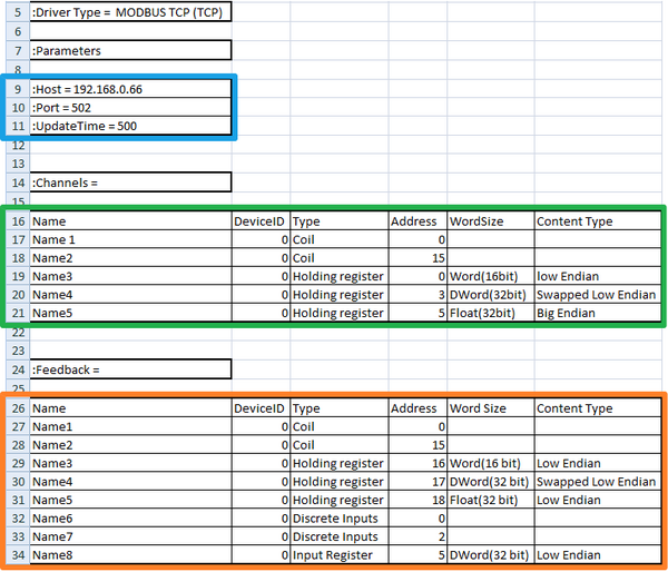
The Modbus protocol in iRidium enables control of any number of controllers. For that it was created the universal system of data import which creates the list of commands and feedback channels for the Modbus driver in the Exel table. This table is saved in the CSV format and can be imported in iRidium projects as a new Modbus device:
download the template of importing Modbus commands
- In the block marked blue, indicate the IP-address, port and frequency of transactions for connection to the controller via Modbus TCP. If you use another driver, copy its name from GUI Editor and indicate it in the first string of the template instead of MODBUS TCP (TCP)
- In the block marked green, form the list of commands (Commands) which you need to create in the project device tree. Each string is a command with the name and a number of settings (you can see more information in the section " Sending Commands and Reading Data by the Modbus protocol ")
- In the block marked orange, form the list of feedback channels (Feedbacks) which you need to create in the project device tree. Each string is a command with the name and a number of settings (you can see more information in the section " Sending Commands and Reading Data by the Modbus protocol ")
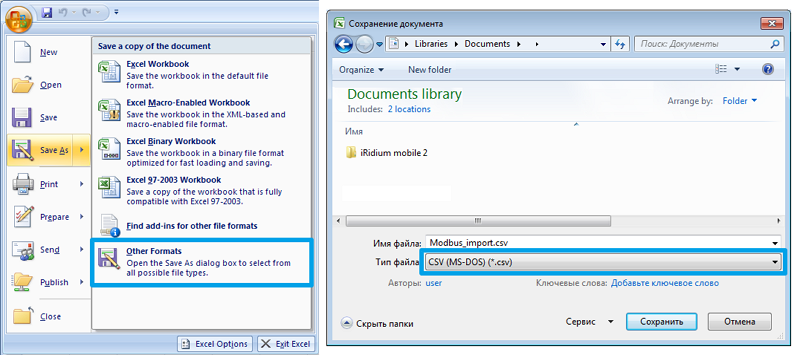
When the list of commands and channels is formed save the Exel table in the *.CSV format:
As a result you will have the file ready for importing in iRidium. Go to iRidium GUI Editor, create a new project and use File > Import. Select the created CSV file and confirm import of data to your project.
Sending Commands and Reading Data by the Modbus protocol
According to the standards of the Modbus protocol iRidium refers to the following types of variables - Type:
- Coil Register – one bit, data reading and writing
- Holding Register - 16-bit word, data reading and writing
- Discreet Inputs - one bit, data reading only
- Input Register - 16-bit word, data reading only
There is a possibility to change the length of the word you want to send to the controller up to 32 bit. You can use word size setting in the properties of iRidium commands and channels - Word Size (in the standard Modbus protocol only 16-bit words are used):
- Word (16-bit) - 16-bit word corresponding to the standard Modbus protocol
- DWord (32-bit) - 32-bit word consisting of two standard Word registers
- Float (32-bit) - 32-bit word where data is written with the help of ASCII symbols
As data writing in bytes can be performed in different sequences there is classification of data writing sequences - Content Type (Low Endian is used by default):
- Low Endian – sequence of bytes typical for the standard Modbus protocol where data writing begins with the lower byte and ends with the higher byte (b1, b2, b3, b4)
- Big Endian - data writing begins with the higher byte and ends with the lower byte (b4, b3, b2, b1)
- Swapped Low Endian and Swapped Big Endian – sequence of bytes corresponds to the higher definitions but bits in each word are written in the reversed order (n,...,1)
To send data to registers iRidium uses Commands и Feedbacks where you are required to indicate properties of the register you send data to. Commands and channels are created on the output of the Modbus driver and are sent to the device which properties are indicated in the driver settings.
Sending and receiving data about the state of variables are performed by the drive on the basis of the list of commands and channels it has. Initiation of command sending is performed by graphic items the commands are assigned to. Data received from the controller can affect properties of the graphic items and can be displayed in the text field of the graphic items as values.
Frequency of transaction initiation (requesting data from the controller) is indicated on the stage of setting up connection.
The following graphic items can be used for controlling Modbus variables and setting up interfaces:
| Button | Sending fixed values; displaying data received from the controller |
| Level | Sending values from the preset range by the slider; displaying the current value by the position of the slider |
| Trigger Button | Switching between two fixed values indicated at the item setting |
| Up/Down Button | Incrementing/decrementing the current value by the preset value in the preset range. The range and the step of increment/decrement are set at the item setting. |
| Multistate Button | Sending fixed values and receiving data accompanied by animation |
| Multistate Level | Sending and receiving values in the preset range where each value or group of values has its own image |
| Edit Box | Inputting a string of data to be sent to the bus |
| Joystick | Controlling RGB with the help of ColorPicker |
Creating Commands for Controlling Modbus Variables
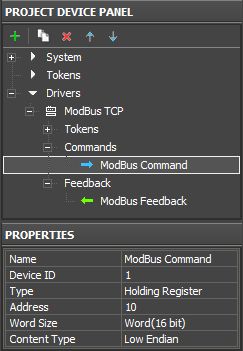
1. Create a command in the project tree and indicate its properties:
(command properties will be described in detail in examples of communication with controllers)
| Name | a command name (at random) |
| Device ID | an address of the dependent device the command is addressed to (slave id) |
| Type | a type of the register the command refers to |
| Address | an address of the controlled register |
| Word Size | size of the transferred word, usually: Word 16-bit |
| Content Type | order of bytes in the word, usually: Low Endian |
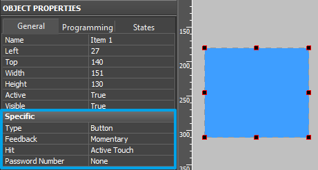
2. Create a graphic item which will initiate command sending
(item properties depend on the command type and control tasks):
Selection of the item type depends on the behavior it should have. Selection of the item feedback type (Feedback) affects processing and displaying data which were received by the item from the controller. Main Feedback types used:
- Momentary – not to display data received from the channel but change the item state when pressing on it (return to the initial state when releasing it).
- Channel – to display data received from the channel. Data can be output in the item text field; they can affect its state (switch the state depending on the received values) or affect other item properties.
The rest feedback types have specific purposes and are used less frequently.
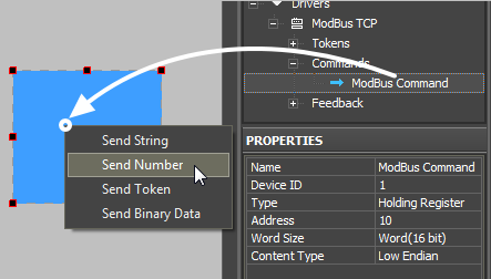
3. Drag the command onto the graphic item
Assigning the command to the item is performed by the Drag&Drop method.
When dragging the command the window of selecting general data type, which are sent to the controller, appears:
- Send String – send data strings in the UTF-8 format (it is used when sending fraction values to registers holding numbers with floating point, Float 32-bit)
- Send Number – send numbers in the decimal format (it is used when sending any whole numbers to Coil or Holding registers. The number for sending is fixed and it is indicated when assigning the command to the graphic item.)
- Send Token – send values taken by one of the graphic item properties or a global token to the bus (for example you can select sending the current slider position of the Level graphic item. It is used for regulating values in Holding registers and when working with Trigger Buttons and Up/Down Buttons)
- Send Binary Data – it is not used for Modbus
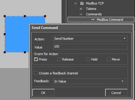
4. Input data for sending and indicate the event the data will be sent at
If it is necessary to read data from the same register mark the "Create Feedback Channel" event, indicate the item property the feedback channels will affect:
At the command adding indicate not only the value to be sent to the register but also the event the value will be sent at in the dialog window:
- Press - pressing on the item (sending telegrams on pressing)
- Release - releasing the item
- Hold - cyclic data sending when holding the item (additional setting of delay between command sending is required)
- Move - sending data at each slider move (all values taken by Level); it is used for the Level item only.
Creating Channels for Receiving and Displaying the Status of Modbus Variables
1. Create a feedback channel for receiving the Modbus register status
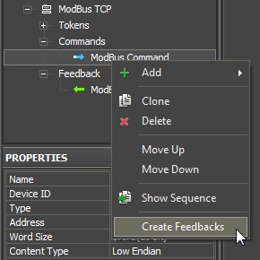
(the channel can be created manually, generated in Project Device Tree with the help of the “CreateFeedbacks” button in the right-click menu)
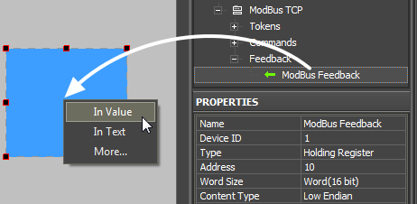
2. Drag the feedback channel on the graphic item
(adding of the feedback channel is performed by dragging it from the tree to the graphic item)
- Channel – it is required to indicate this feedback type (Feedback) in the item properties if data of the channel bound to the item affect the behavior of the item (for example, if data from the bound channel has to be output in the text field; or when receiving “1” from the channel the item has to take the second state – change the image).
Indicate if the item property the feedback channel will affect:
- In Text – values received from the channel should be output as numbers in the text field
- In Value – values received from the channel should affect the item state (change the slider position of Level, switch Button on/off, initiate animation, etc.)
- More… – select more complex way of communication between the channel and item properties (for example, change item coordinates when the channel value is changed)
Emulation of Project Work
Emulator
- is an iRidium application for Windows which can be launched from GUI Editor for testing your projects. Emulator can work both with a license (with connection to the equipment) and without it (when only the project graphic part is functional).
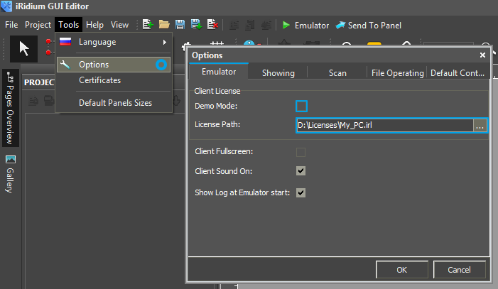
Operation modes for Emulator (see GUI Editor > Tools > Options > Emulator):
- Without the license (Demo Mode: on) – no connection with the controlled equipment.
- With the license (License Path: [...]) – when the license file is selected, all Emulator functions work and there is connection with the controlled equipment.
Indicate the path to the license file for Emulator (GUI Editor > Tools > Options > Emulator):
* When Demo Mode is activated Gui Editor won’t show the message about starting without the connection to the controlled equipment (without a license). Check if there is a license when setting up your project.
Emulator hot keys
- Click F5 to start Emulator.
- Click F8 to open the Emulator settings (password: 2007)
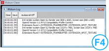
- Click F4 to open the Emulator log.
| For fully functional work of iRidium on your PC it is required to get an iRidium license and activate it for for your PC. Activation of licenses for iPad/iPhone/Mac/Android based or other devices does NOT lead to the automatic licensing of the PC with the installed iRidium Environment. A license for your PC is required for iRidium client on your PC (including Emulator) to work in the fully functional mode. The license should be purchased separately or you can use free For testing purposes you can use free licenses). |
Logging in Windows
iRidium Log is a window where information about iRidium work, error messages and iRidium Script logs (IR.Log) are output in the text format.
To open the iRidium log in Windows, click F4.
Launching Projects on Control Panels
Uploading and launching of iRidium projects on control panels are performed with the help of the iRidium Transfer application installed on your PC. You can also upload your project on the panel from GUI Editor with the help of Transfer.
- Instructions for setting up properties of the iRidium project launch on control panels: Properties for Launching iRidium Projects
- Instructions for uploading iRidium projects on control panels: iRidium Transfer.
- Instructions for setting up iRidium projects on control panel: iRidium App
