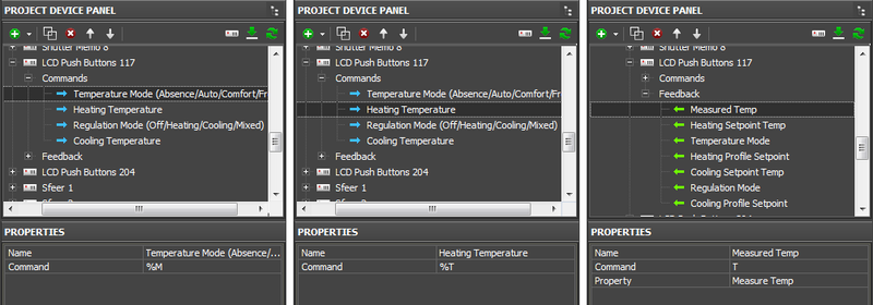
Examples of Controlling Domintell
Contents
Relays
Modules for controlling relays:
| Name: | Description: | |
| DBIR01 | BIR | 8 bipolar relays |
| DMR01 | DMR | 5 monopolar relays |
| DTRP01 | TRP | 4 pulse relays |
| DLED01 | LED | 4 leds driver |
Commands for controlling relays:
| Command: | Description: |
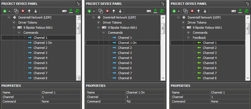
| None | switch the channel |
| %I | activate the channel |
| %O | deactivate the channel |
Ways of control
- 2 buttons (On and Off) - one button for locking the relay, the other – for unlocking. You can set up displaying of the relay current state.
- 1 button (trigger switch) – switches the relay to the state opposite to the current one. You can set up displaying of the relay current state.
Command settings:
| Channel | - channel number |
| Command | None – switch the channel, %I – activate the channel, %O – deactivate the channel |
- commands are assigned to Button and when clicking the button they are sent to Domintell module. Other types of graphic items (not Button) are not used for controlling relays.
Set up relay control:
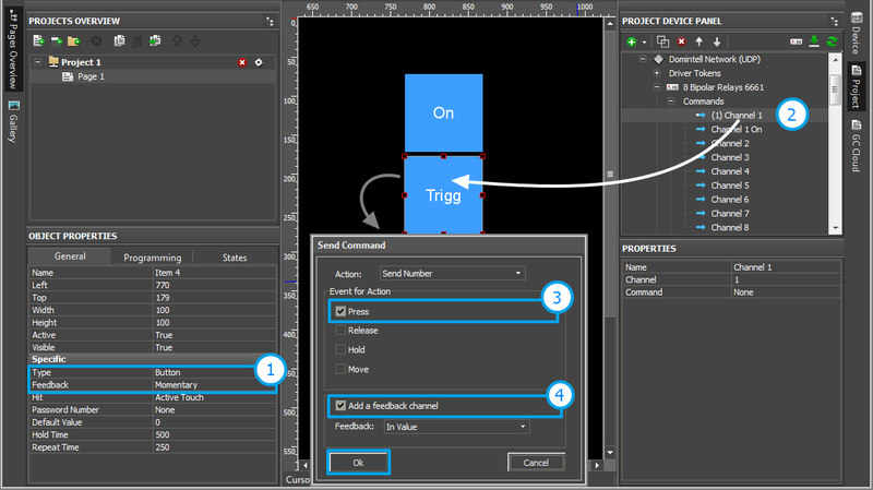
1. Create a button for controlling the relay
- Type: Button
- Feedback: "Momentary" – for the commands %I and %O, "Channel" - for None
2. Select the command of relay control (switch, on, off) and drag it to the button (Drag&Drop)
3. In the dialog window for command assignment select the event for command sending:
- Press – pressing on the item
- Release - releasing the item
- Hold - holding the item
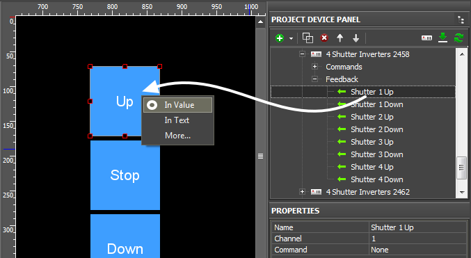
4. To receive feedback from the channel activate "Add a Feedback Channel".
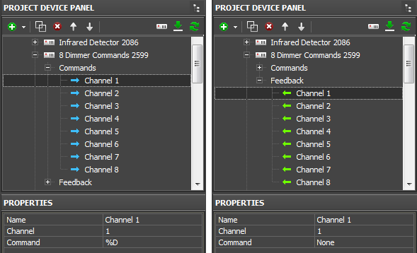
![]() To receive feedback on the items to which the commands %I and %O are assigned, do not use "Create a Feedback Channel", but drag the feedback channel on the item from the Feedbacks tab. It will help to avoid channel duplication. See more information about it below.
To receive feedback on the items to which the commands %I and %O are assigned, do not use "Create a Feedback Channel", but drag the feedback channel on the item from the Feedbacks tab. It will help to avoid channel duplication. See more information about it below.
Set up displaying of the relay status:
Relay switch from the locked state to the unlocked can be displayed by changing the button state (State 1 = Off / State 2 = On).
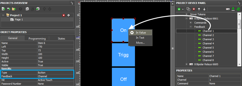
1. Create a button
- Type: Button
- Feedback: Channel
2. Select the feedback channel in the tab Feedbacks and assign it to the button:
- In Value – the button will change the state when the relay status changes (0/1)
- In Value + Template of data output – the relay status is written in the item text field. You can indicate the measurement units, etc. there too.
- In Text – the relay status is written in the item text field substituting the whole text.
Motorized Shutters
Modules for controlling shutters:
| Name: | Description: | |
| DTRV01 | TRV | 4 shutter inverters (up/down) |
| DTRP02 | TPV | 4 shutter inverters(up/down) |
| DTRVBT01 | V24 | 1 DC shutter command (up/down) |
Commands for controlling shutters:
| Command: | Description: |
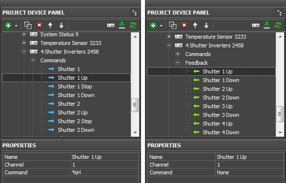
| None | switch the channel |
| %O | turn off the channel (stop) |
| %H | turn on the channel (up) |
| %L | turn on the channel (down) |
Ways of controlling shutters:
- 3 buttons (Open, Close, Stop) – each sends its own command to the shutters. You can display the direction.
- 2 buttons (Open/Stop, Close/Stop) - activate shutters at the first pressing and stop them at the second pressing.
Command settings:
| Channel | - номер канала |
| Command | - up/down/stop/switch) |
- commands are used with Buttons. Other types of graphic items (not Button) are not used for controlling shutters.
These are commands available for the modules for controlling shutters in the Domintell systems. The commands are used together with interface items Buttons. Button sends command to the Domintell module. Other types of graphic items are not used for controlling shutters.
Set up shutters control:
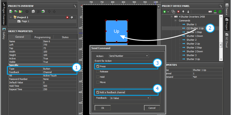 1. Create buttons for controlling shutters
- Type: Button
- Feedback: Channel
2. Select a control command (up, down, stop) and drag the command on the button (Drag&Drop)
3. Select the event for sending in the dialog window for assigning commands:
- Press – pressing on the item
- Release - releasing the item
- Hold - holding the item
4. To receive feedback from the channel activate "Add a Feedback Channel".
Set up display of the shutters status:
The shutters state (Up/Stop or Down/Stop) can be displayed by changing the Button state.
1. Create a display button
- Type: Button
- Feedback: Channel
2.Select the feedback channel in the Feedbacks tab and assign it to the button:
- In Value – the button changes its state when the shutters change the status (Up/Stop or Down/Stop)
- In Value + Templates of value output – the status is written in the item text field. You can indicate units of measurements there too.
- In Text – the status (0/1) is written in the item text field substituting all the text there
Dimmers
Modules for controlling dimmers:
| Name: | Description: | |
| DDIM01 | DIM | 8 dimmer commands |
| DOUT10V01 | D10 | 0/1-10V dimmer module |
</div>
Commands for dimmer control:
| Command: | Description: |
| None | switch the channel |
| %I | turn on the channel |
| %O | turn off the channel |
| %D | dim the channel (0...100) |
| %I%D | increment by percent (0...100%) |
| %O%D | decrement by percent (0...100%) |
| %DB | start dimming |
| %DE | stop dimming |
Ways of controlling dimmers:
- 2 Buttons (On and Off) – one is for 100% dimmer brightness, the other – for 0%.
- 1 Button for trigger switching. It sets the dimmer to the state opposite to the current one (between 0% and 100%)
- 1 Button for gradual dimming – to start dimming when pressing the button, to stop dimming when releasing the button
- Level – to set up a random value of the dimmer brightness in the range from 0 to 100% by moving the slider
- Up/Down Buttons – to increment or decrement the dimmer brightness by the preset percent from its current value
Different ways of controlling dimmers can be combined.
Command settings:
| Channel | - the channel number |
| Command | - the command to the channel None, %I, %O, %D [v], %I%D [v], %O%D [v], %DB, %DE [v] – the command requires inputting the value (Value) when dragging on the graphic item. |
Set up dimmer control with the help of the command %D:
![]() With the help of the command %D and graphic items (Button, Level, Up/Down Button, Trigger) you can set up any way of controlling the level (on, off, Inc/Dec, dimming, switching). You do not need to create other commands (%I, %O, %I%D, %O%D).
With the help of the command %D and graphic items (Button, Level, Up/Down Button, Trigger) you can set up any way of controlling the level (on, off, Inc/Dec, dimming, switching). You do not need to create other commands (%I, %O, %I%D, %O%D).
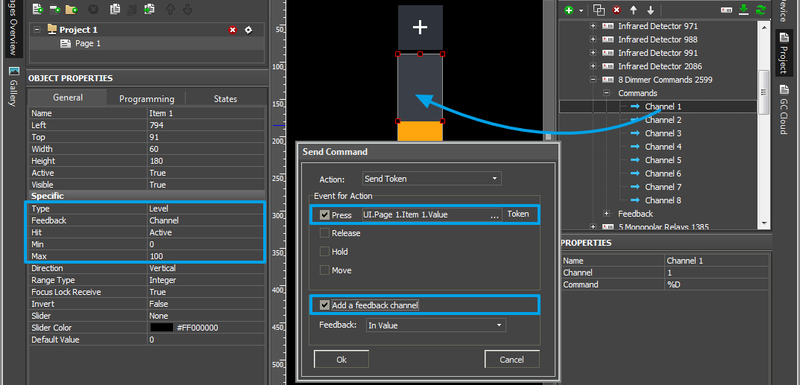
To use other graphic items, they have to be set as Level (assign the command and feedback channel, indicate the regulation range or other required item properties).
1. Set up Level for dimmer control. Set up its operation range:
- Type: Level
- Feedback: Channel
- Min: 0, Max: 100
2. Drag the command %D to the item (Drag&Drop)
3. Select the event at which the value will be sent to the dimmer (Press + Release are usually used)
- Press – pressing on the item
- Release - releasing the item
- Move – moving the slider (Attention! This event generates many values for sending to the bus)
Set up display of the dimmer status:
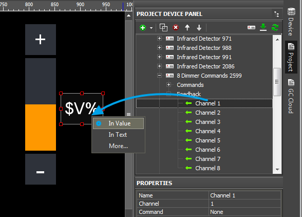
Change of the dimmer brightness can be displayed by changing the number on the display button or by moving the slider.
1. Create:
- a display Button (Type: Button) or Level (Type: Level, Min: 0, Max: 100).
- Feedback: Channel
2. Drag the Feedback of the Domintell driver on the item and select its way of affecting the item:
- In Value – the slider moves in the range from 0 to 100
- In Value + Templates of value output – the brightness value is written in the item text field. You can indicate units of measurements there too.
- In Text – the status is written in the item text field substituting all the text there
Temperature: LCD Touch Screens and Sensors
LCD, modules for temperature measuring:
| Name: | Description: | |
| DLCD03 | LC3 | multifunktion LCD |
| DPBTLCD0x | PBL | LCD push buttons |
| DTSC01_03 | TSB | touchscreen |
| DTSC04 | LT4 | TFT touchscreen with video |
| DTEM01 | TE1 | temperature sensor |
| DTEM02 | TE2 | temperature sensor with 2*16 char LCD |
Commands of controlling temperature:
| Commands: | Description: | Feedbacks: | Description: |
| %R | Set Regulation Mode: 0 = OFF |
U, Mode | Regulation Mode: 0 = OFF |
| %T | Heating setpoint | T, Setpoint Temp | Heating Setpoint Temperature |
| %U | Cooling setpoint | U, Setpoint Temp | Cooling Setpoint Temperature |
| %M | Temperature mode: 1 = ABSENCE |
T, Mode | Temperature Mode: 1 = ABSENCE |
Variables of the channel of controlling temperature:
| Module | - a command name |
| Command [v] |
Set up control of temperature modes:
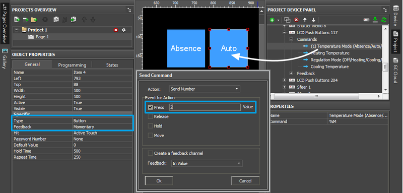
1. Create Button for controlling temperature modes.
- Type: Button
- Feedback: Momentary
2. Drag the command for controlling the temperature mode (%M) on the button (Drag&Drop)
3. In the dialog window select the event at which the command will be sent:
- Press – pressing on the item
- Release - releasing the item
- Hold - holding the item
4. Indicate the value for sending:
Type of Regulation:
|
Temperature mode:
|
Set up control of the temperature value:
1. Create Level to control the temperature. Up/Down Buttons can increment/decrement the temperature. Button can set up a particular temperature value.
- Type: Level
- Feedback: Channel
- Min: 5, Max: 35 (or some other regulation range)
- Set up the command for controlling the temperature value (%T)
2. Drag the command (%T or %U) on the item (Drag&Drop)
- For Button: select Send Number in the window for assigning commands. For Level: Send Token will be selected automatically
3. Select the event at which the command will be sent (Press + Release are usually used for Level)
- Press – pressing on the item
- Release - releasing the item
- Move – moving the slider (Attention! This event generates many values for sending to the bus)
Variables of the temperature status:
| Command T: Measured Temp – the sensor temperature |
Command U: Setpoint Temp - the current temperature setting (degrees) |
Set up display of temperature data:
Change of the temperature value and temperature mode can be displayed differently: on level or on other graphic item as text or number.
1. Create
- a display button (Type: Button) or Level (Type: Level, Min: 5, Max: 35).
- Feedback: Channel
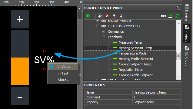
2. Drag the channel from the Feedbacks tab on the item indicating:
- In Value – for Level, the slider moves displaying the current temperature status
- In Value + Templates of value output – the temperature value is written in the item text field. You can indicate units of measurements there too.
- In Text – the value is written in the item text field substituting all the text there
Other
The list of modules which you can control directly from iRidium:
- Emulation of clicking (button, input module)
- DPBUT1 (BU1), DPBUT2 (BU2), DPBUT4 (BU4), DPBUT6 (BU6), DISM04 (IS4), DISM08 (IS8)
- Sound module
- DAMPLI01 (AMP)
- Relay function
- DBIR01 (BIR), DMR01 (DMR), DTRP01 (TRP), DLED01 (LED)
- Shutters (reverse drive)
- DTRV01 (TRV), DTRP02 (TPV), DTRVBT01 (V24)
- Dimmer function
- DDIM01 (DIM), DOUT10V01 (D10)
- Temperature: reading the status and setting up modes
- DLCD03 (LC3), DPBTLCD0x (PBL), DTEM01 (TE1), DTEM02 (TE2), DTSC01_03 (TSB), DTSC04 (LT4)
- Display of statuses
- DMOV01 (DET), DIN10V01 (I10), DISM04 (IS4), DISM08 (IS8)
- System functions
- SOFT_VAR (VAR), SYS_VAR (SYS), MEM (MEM), SFE (SFE), ZON (ZON)
- Fan coil units
- FAN01 (FAN)
Work with modules which are not included in the Domintell Light Protocol list:
- If you don’t see your modules in the Light Protocol list, it means direct control of the module is not supported.
- It is required to send the "%I" command to Input, which controls your module: emulate clicking the buttons set up for control of the module in the Domintell system.
- For example, one of the modules which do not support direct control via the Domintell Light Protocol is DIREMIT01. To send IR commands through the module it is required to set up connection between DIREMIT01 and Input (through Domintell Programation). Thus, it is enough to simulate the Input activation.
