Examples of Controlling Equipment of the HDL-BUS Pro Bus
For controlling equipment in the HDL-BUS Pro bus use the sets of commands which are set up separately for each device in the bus.
The sets of commands for controlling some devices in the HDL-BUS Pro bus are strictly regulated and their creation is obligatory for correct work with the device. The present instructions present command settings for communication with various controlled device types in the HDL-BUS Pro bus.
Contents
- 1 Relay Modules
- 2 Toggle Relays
- 3 Dimmers, DMX Controllers
- 4 Sensors, Input/Output Modules, IR Transmitters
- 5 Floor Heating, Conditioners – Control via DLP-panels or 6-channel Modules
- 6 Power Meters
- 7 Security Modules
- 8 Scenes and Sequences for Different Equipment
- 9 SMS Modules with Ethernet Interfaces
- 10 Gateways and Bridges for Integration with Third-party Equipment
- 11 Logic Controllers
- 12 How to Decrease Load on HDL Equipment When Requesting States of Variables
Relay Modules
Download: example of controlling a relay (project). 0,7 Mb
Relays, magnetic relays, modules for controlling ballasts and combined loads with built-in relays
Operation codes: Single Channel Control, Single Channel Read Target, Single Channel Read Actual,
Scene Control, Sequence Control
Control of relay modules in the HDL-BUS Pro bus is performed with the help of the set of commands and feedback channels. Commands are used for setting up the relay state (on/off), Feedbacks – for receiving the relay status and displaying it in the iRidium project. It is also required to have initialization command of the relay state.
Creation of Commands for Relay Control in the iRidium Project Tree
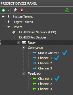
When working with a relay module in the HDL-BUS Pro bus you need to create the following items of the project device tree:
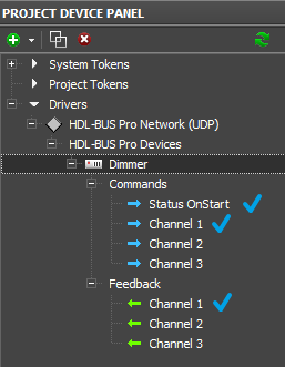
Commands for setting up states of relay channels (Commands). The number of commands should correspond to the number of relay module channels. Indicate the number of the controlled relay channel and speed of switching from the locked state to the unlocked in the command settings.
The feedback channel for receiving data about the relay state (Feedbacks). Indicate the number of the relay channel which state this Feedback should display in the channel settings.
Request for the relay state at the iRidium project launch will be sent once at the launch. In return the relay will send states of all its channels. In the process of project work the relay will automatically inform about the state change and forced requests are not required.
Commands for Setting up the Relay State
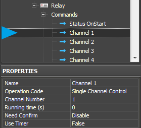
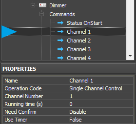
Commands for setting up the relay state can be created manually or you can use the ready ones received after scanning of the HDL-Bus Pro network. You can duplicate commands in the tree with the help of the Clone button on Project Device Panel.
- Operation Code: Single Channel Control – the command for controlling the relay state (setting up the state)
- Channel Number: 1...n – the number of the relay module channel which state it is required to set up
- Running Time (ms): 0...n – length of command execution (time of switching from the locked state to the unlocked and back), it is usually used when working with dimmers
- Need Confirm: Disable/Enable – necessity of monitoring the command delivery. It is NOT recommended to use with key modules when working via the Internet (slow connection).
- Use Timer: False/True – sending the command in cycles, on timer. It is used for cyclic value or command sending at the project launch. It is usually not used when working with Operation Code: Single Channel Control.
Feedback Channels for Reading the Relay State
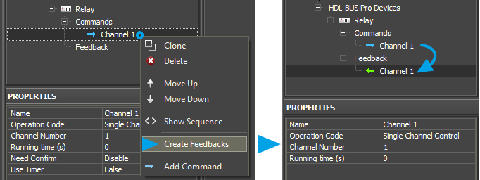
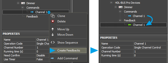
Feedback channels which will display the state of controlled relay channels in iRidium projects are formed on the basis of commands for controlling the relay with the help of the Create Feedback option.
Indicate the number of the relay channel you want to receive data from in the settings of feedback. The Running Time (ms) parameter is not considered.
![]() Holding the Shift button you can highlight the range of commands in the project device tree and form feedback channels for them. You can also create these channels manually or use the function for automatic creation of channels when dragging commands to graphic items (it is described below).
Holding the Shift button you can highlight the range of commands in the project device tree and form feedback channels for them. You can also create these channels manually or use the function for automatic creation of channels when dragging commands to graphic items (it is described below).
Request for the Relay State at the Project Launch or Opening a Page
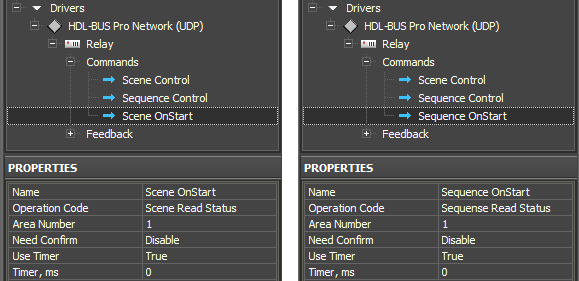
The command sends the request for the status of all (or one) relay channels in the HDL-BUS Pro bus. The command is obligatory for correct displaying of the relay state at the iRidium project launch!
When using the network scanning it is created automatically.
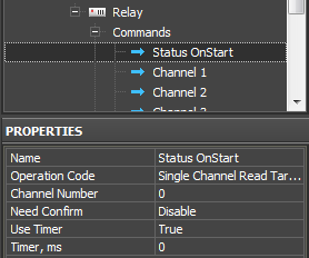
Example of creating the command for initialization of the relay channels at the iRidium project launch:
- Operation Code: Single Channel Read Target – the forced request for the relay module state
- Channel Number: 0 – indicating zero we request the current state of ALL relay channels. If you indicate value 1...n you can request the state of some particular relay channel.
- Need Confirm: Disable/Enable - necessity of monitoring the command delivery. It is NOT recommended to use with key modules when working via the Internet (slow connection).
- Use Timer: True - sending the command on timer. The moment of activating the timer is defined by the next string.
- Timer, ms: 0 – the moment of timer activation. In our case it is required to activate the timer only at the project launch and that is why we indicate zero.
This request command is not assigned to graphic items as it is activated only on timer at the project launch without interfering of the graphic interface. The command should be created in the project tree; no more additional actions are required. Relay answers will come to the created feedback channels with the Single Channel Control operation code.
![]() For avoiding overload of the bus at the iRidium project launch you can make the request for the state of relay channels when opening the page for controlling the relay (sending the request when pressing on the button pf opening the page with graphic items controlling the relay and displaying its status). In this case sending on timer should be turned off (Use Timer: False), and assign the command with the help of the Drag&Drop method to the button which opens the required page. When assigning the command select "Send Number", mark the "Press" event, leave the field for inputting values for the "Press" event empty.
For avoiding overload of the bus at the iRidium project launch you can make the request for the state of relay channels when opening the page for controlling the relay (sending the request when pressing on the button pf opening the page with graphic items controlling the relay and displaying its status). In this case sending on timer should be turned off (Use Timer: False), and assign the command with the help of the Drag&Drop method to the button which opens the required page. When assigning the command select "Send Number", mark the "Press" event, leave the field for inputting values for the "Press" event empty.
Activation of Relay Module Scenes and Sequences
Work with scenes and sequences is set up similarly for all HDL-BUS Pro devices with Scene and Sequence support. You can find information about setting up scenes and sequences in the Scenes and Sequences for HDL-BUS Pro Equipment section.
Relating Relay Commands and Channels with Graphic Items
Command sending is activated by the graphic item the command is assigned to. For sending values to the relay channels you can use:
- Buttons – one for locking the relay, the other one for unlocking it. You create two buttons linked with one assigned command. The buttons can display the current status of the controlled relay after certain setting up.
- Trigger Button - it switches the relay state to the opposite on at each pressing.
Setting up the Relay State by Button
Create a Button type graphic item with 1 or 2 states. With its help you can send the value to the relay channel:
- 0 – lock the relay channel or
- 100 – unlock the relay channel
Value selection is made in the process of assigning the command to the graphic item.
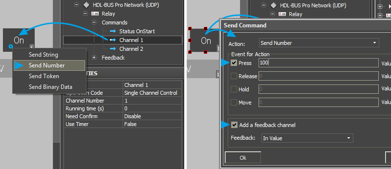
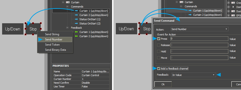
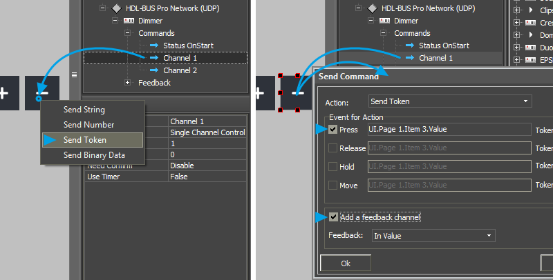
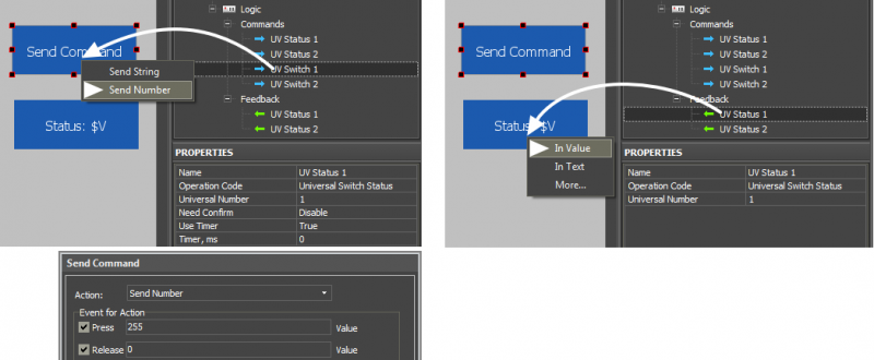
Drag the command from the device tree to iRidium GUI Editor Workspace. When assigning the command to one of the created buttons select Send Number - send the value (constant) to the relay channel in the window of command assigning:
In the open dialog window indicate the value which is necessary to be sent to the channel and the interface event at which the command for setting the value should be sent:
- Press – the command is sent when pressing on the button
- Release - the command is sent when releasing the button
Activation of "Add a Feedback Channel" ("Create a Feedback Channel") should be made only if the button should both send the command to the relay and display the relay state by switching from State 1 to State 2 (channel assigning - In Value). The current relay state can be also output in the item text field when assigning the channel In Text in the dialog window.
- If the button should change its state when changing the relay status, indicate Feedback: Channel in the settings of the graphic item (the item state will depend on the feedback channel state).
- If the button should not change the state when changing the relay status, indicate Feedback: Momentary (the item state will change when pressing on the item and will go back to the initial state when releasing the item)
The created command is displayed in the Programming tab of the Object Properties window – graphic item settings. If it is necessary the command can be changed from the Press event to Release when dragging it by the text field.
Trigger Relay Switching by Trigger Button
Create a Trigger Button type graphic item with 2 states. You will be able to switch two relay states:
- 0 - lock the relay channel or
- 100 - unlock the relay channel
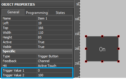
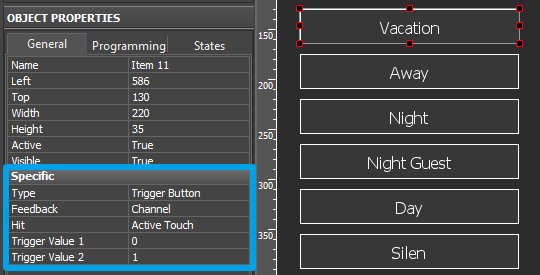
In the settings of graphic item indicate Trigger Value 1 and 2 – values the button will switch at each pressing. For HDL-BUS Pro relay modules they can be only 0 and 100.
Trigger Button always has 2 states (they are set in the States tab of graphic item properties). State 1 corresponds to Trigger Value 1, State 2 - Trigger Value 2.
In the Trigger Button settings select Feedback:Channel so the trigger could display the actual variable status by changing its state.
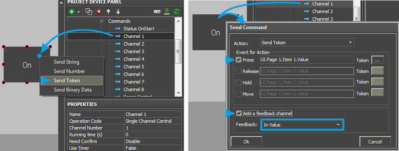
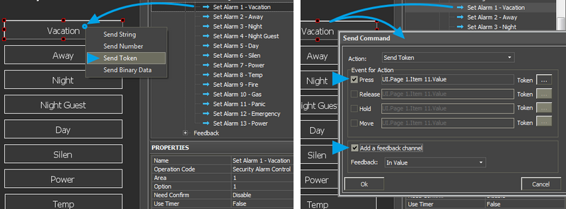
The command is assigned to the graphic item using the Send Token event (send variable value), as it is required to send one of the values indicated when setting up the graphic item at each pressing.
![]() When working with Trigger Buttons it is required to have the feedback channel (activate "Add A Feedback Channel" with channel assigning "In Value"). It should be done due to the fact that the trigger selects the next value for sending on the basis of the current relay state and it will not work without the feedback channel!
When working with Trigger Buttons it is required to have the feedback channel (activate "Add A Feedback Channel" with channel assigning "In Value"). It should be done due to the fact that the trigger selects the next value for sending on the basis of the current relay state and it will not work without the feedback channel!
The feedback channel can be dragged to the graphic item in the process of working with the command or from the project device tree. At that select "In Value" as the way of assigning.
Displaying the Current Relay State
The current relay state can be displayed on any graphic item but it is more convenient to used a display button with 1 state for this. If it is required to display of the relay status by changing the graphic item state, use Button with 2 states.
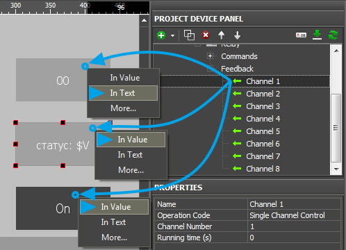
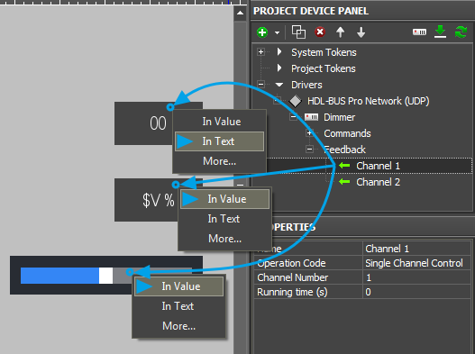
- For the display button in which text field there should be: 1 (to lock the relay) or 0 (to unlock the relay), the feedback channel is assigned by the "In Text" event – it will substitute any text which is in the text field of the item by default.
- For the display button in which text field there should be some symbols besides the current relay value, the feedback channel is assigned by the "In Value"event and indicate the template of value processing - $V in the text field of each graphic item state. The template will be substituted by the value received from the channel at project launch. At that the other text in the item field will not be deleted.
- For the button with 2 states, the feedback channel is assigned by the "In Value" event. When receiving 1 from the channel (the relay is locked), the item will automatically change to State 2 (you can set up states in the States tab of graphic item properties).
Toggle Relays
Download: example of controlling a toggle relay (project). 0,7 Mb
Toggle relays for controlling shutters, roller blinds, curtains, etc. (2 channels)
Operation codes: Curtain Control, Curtain Read Status
Control of toggle relays modules in the HDL-BUS Pro bus is performed with the help of the set of commands and feedback channels. Commands are used for setting up the relay state (stop/up/down), Feedbacks – for receiving the relay status and displaying it in the iRidium project. It is also required to have initialization command of the relay state.
Creation of Commands for Toggle Relay Control in the iRidium Project Tree
When working with a toggle relay in the HDL-BUS Pro bus you need to create the following items of the project device tree:
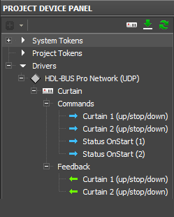
Commands for setting up relay states (Commands). Two commands should be created in the tree: one for each toggle channel. The values for sending by the commands are: 0 – stop, 1 – up, 2 - down.
The feedback channel for receiving data about the relay state (Feedbacks). Indicate the number of the relay toggle channel which state this Feedback should display in the channel settings. There can be 3 states: 0 - stop, 1 - up, 2 – down.
Request for the relay state at the iRidium project launch will be sent once at the project launch. In return the relay will send the state of the toggle channel. In the process of project work the relay will automatically inform about the state change and forced requests are not required. Requests are created for each channel of the toggle relay.
Commands for Setting up the Relay State
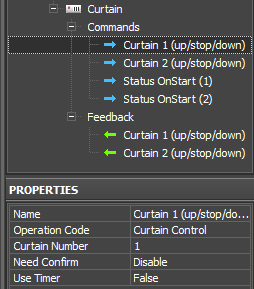
Commands for setting up the relay state can be created manually or you can use the ready ones received after scanning of the HDL-Bus Pro network. Create two commands for 2 relays with two toggle channels with the following properties:
- Operation Code: Curtain Control – the command for controlling the toggle relay state
- Channel Number: 1 or 2 – the number of the toggle channel
- Need Confirm: Disable/Enable – necessity of monitoring the command delivery. It is NOT recommended to use with key modules when working via the Internet (slow connection).
- Use Timer: False/True – sending the command in cycles, on timer. It is used for cyclic value or command sending at the project launch. It is usually not used when working with Operation Code: Curtain Control.
Feedback Channels for Reading the Relay State
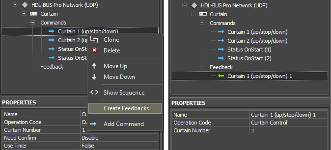
Feedback channels which will display the state of toggle channels in iRidium projects are formed on the basis of commands for controlling the relay with the help of the Create Feedback option.
Indicate the number of the toggle channel you want to receive data from in the settings of feedback.
![]() Holding the Shift button you can highlight the range of commands in the project device tree and form feedback channels for them. You can also create these channels manually or use the function for automatic creation of channels when dragging commands to graphic items (it is described below).
Holding the Shift button you can highlight the range of commands in the project device tree and form feedback channels for them. You can also create these channels manually or use the function for automatic creation of channels when dragging commands to graphic items (it is described below).
Request for the Relay State at the Project Launch or Opening a Page
The command sends the request for the status of the relay toggle channel in the HDL-BUS Pro bus. Two commands should be created for two toggle channels. The commands are obligatory for correct displaying of the relay state at the iRidium project launch!
When using the network scanning they are created automatically.
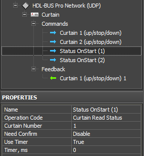
Example of creating the command for initialization of the relay toggle channels at the iRidium project launch:
- Operation Code: Curtain Read Status – the forced request for the relay state
- Channel Number: 1 or 2 – indicating 1 we request the state of the first relay channel, 2 - the state of the second toggle channel.
- Need Confirm: Disable/Enable - necessity of monitoring the command delivery. It is NOT recommended to use with key modules when working via the Internet (slow connection).
- Use Timer: True - sending the command on timer. The moment of activating the timer is defined by the next string.
- Timer, ms: 0 – the moment of timer activation. In our case it is required to activate the timer only at the project launch and that is why we indicate zero.
This request command is not assigned to graphic items as it is activated only on timer at the project launch without interfereing of the graphic interface. The command should be created in the project tree; no more additional actions are required. Toggle channel answers will come to the created feedback channels with the Single Curtain Control operation code.
![]() For avoiding overload of the bus at the iRidium project launch you can make the request for the state of relay channels when opening the page for controlling the relay toggle channel (sending the request when pressing on the button for opening the page with graphic items controlling the relay and displaying its status). In this case sending on timer should be turned off (Use Timer: False), and assign the command with the help of the Drag&Drop method to the button which opens the required page. When assigning the command select "Send Number", mark the "Press" event, leave the field for inputting values for the "Press" event empty.
For avoiding overload of the bus at the iRidium project launch you can make the request for the state of relay channels when opening the page for controlling the relay toggle channel (sending the request when pressing on the button for opening the page with graphic items controlling the relay and displaying its status). In this case sending on timer should be turned off (Use Timer: False), and assign the command with the help of the Drag&Drop method to the button which opens the required page. When assigning the command select "Send Number", mark the "Press" event, leave the field for inputting values for the "Press" event empty.
Activation of Toggle Relay Scenes and Sequences
Work with scenes and sequences is set up similarly for all HDL-BUS Pro devices with Scene and Sequence support. You can find information about setting up scenes and sequences in the Scenes and Sequences for HDL-BUS Pro Equipment section.
Relating Relay Commands and Channels with Graphic Items
Command sending is activated by the graphic item the command is assigned to. For setting up values of the toggle relay channel you can use:
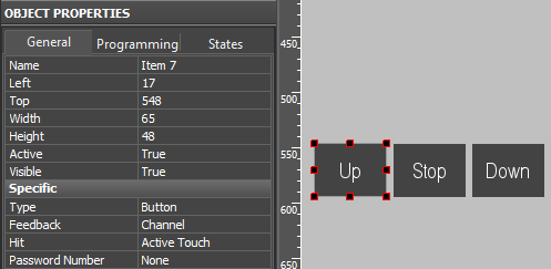
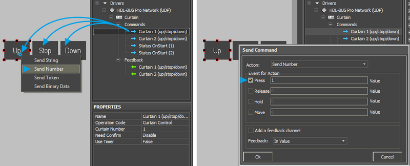
- Button – create three Buttons, for sending Up, Stop, Down commands. The buttons are linked with one command in the project tree (Curtain Control). Value selection is made when dragging commands to graphic items.
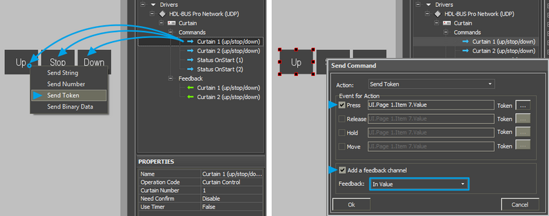
- Trigger Button – create three buttons for sending Up, Stop, Down commands with displaying information about the current relay state (Buttons cannot do it to the full extent).
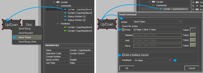
- Trigger Button - it switches the Up/Down mode, the button for controlling the Stop mode.
Setting up the Relay State by Button
Create a Button type graphic item with 1 or 2 states. With its help you can send the value to the relay channel:
- 0 – lock the relay channel or
- 100 – unlock the relay channel
Value selection is made in the process of assigning the command to the graphic item.
Drag the command from the device tree to iRidium GUI Editor Workspace. When assigning the command to one of the created buttons select Send Number - send the value (constant) to the relay channel in the window of command assigning:
In the open dialog window indicate the value which is necessary to be sent to the channel and the interface event at which the command for setting the value should be sent:
- Press – the command is sent when pressing on the button
- Release - the command is sent when releasing the button
Activation of "Add a Feedback Channel" ("Create a Feedback Channel") should be made only if the button should both send the command to the relay and display the relay state by switching from State 1 to State 2 (channel assigning - In Value). The current relay state can be also output in the item text field when assigning the channel In Text in the dialog window.
- If the button should change its state when changing the relay status, indicate Feedback: Channel in the settings of the graphic item (the item state will depend on the feedback channel state).
- If the button should not change the state when changing the relay status, indicate Feedback: Momentary (the item state will change when pressing on the item and will go back to the initial state when releasing the item)
The created command is displayed in the Programming tab of the Object Properties window – graphic item settings. If it is necessary the command can be changed from the Press event to Release when dragging it by the text field.
Switching States of Toggle Relays by Button
It is the simplest variant using which does not provide displaying of the toggle relay current state (it can be done with the help of project variables, but not in a standard way).
Create three Buttons with 1 or 2 states. These buttons will send three value to the relay:
- 0 – unlock the contacts (stop)
- 1 – move up (up)
- 2 – move down (down)
In the properties of all buttons indicate Feedback: Momentary - the item state will change when pressing on the item and will go back to the initial state when releasing the item.
Selection of the value which should be sent by each button is made in the process of assigning the command for controlling the relay state to the graphic item.
Drag the command from the device tree to iRidium GUI Editor Workspace. When assigning the command to one of the created buttons select Send Number - send the value (0, 1 or 2) to the relay channel in the window of command assigning:
In the open dialog window indicate the value which is necessary to be sent to the channel and the interface event at which the command for setting the value should be sent:
- Press – the command is sent when pressing on the button
- Release - the command is sent when releasing the button
Activation of "Add a Feedback Channel" ("Create a Feedback Channel") should be made only if the button should both send the command to the relay and display the relay state by switching from State 1 to State 2 (channel assigning - In Value). The current relay state can be also output in the item text field when assigning the channel In Text in the dialog window.
The created command is displayed in the Programming tab of the Object Properties window – graphic item settings. If it is necessary the command can be changed from the Press event to Release when dragging it by the text field.
Switching States of Toggle Relays by Trigger Button
In this case triggers are not set up in a standard way as they can store only two values and toggle relays work with three values - 0, 1 and 2. In this case using of triggers makes it possible to display the current operation mode of the toggle relay channel. Three items are set up as Radio Buttons – when activating one of the buttons from the group the other buttons are deactivated automatically.
Create three Trigger Button type graphic items with 2 states.
In the item properties indicate the following:
- for the Stop button - Trigger Value 1 and 2: 0 и 0, Feedback: Invert Channel
- for the Up button - Trigger Value 1 and 2: 1 and 1, Feedback: Invert Channel
- for the Down button - Trigger Value 1 and 2: 2 and 2, Feedback: Invert Channel
Trigger Button always has 2 states (they are set in the States tab of graphic item properties). State 1 corresponds to Trigger Value 1, State 2 - Trigger Value 2. When setting up similar values the trigger will send the same value at each pressing but will become active (change to the second state) only if it receives the value corresponding to the lower value from the relay status channel. Thus the trigger will be active only until it receives the value which equals to Trigger Value 1. It allows you to monitor the toggle relay status.
The command is assigned to the graphic item using the Send Token event (send variable value), as it is required to send one of the values indicated when setting up the graphic item at each pressing.
![]() When working with Trigger Buttons it is required to have the feedback channel (activate "Add A Feedback Channel" with channel assigning "In Value") to display the current toggle relay state.
When working with Trigger Buttons it is required to have the feedback channel (activate "Add A Feedback Channel" with channel assigning "In Value") to display the current toggle relay state.
The feedback channel can be dragged to the graphic item in the process of working with the command or from the project device tree. At that select "In Value" as the way of assigning.
Switching States of Toggle Relays by Trigger Button and Button
In this case you set up two graphic items - Trigger Button and Button. Trigger Button will control switching Up/Down modes, Button is responsible for stopping the relay. It is not possible to perform control with one Trigger Button as it has to send 3 values, and it can store only two.
Item settings:
Trigger Button operates with two values 1 (Up) and 2 (Stop), Button will send 0 (Stop). Select Feedback: Invert Channel for Button so it could take the active state only when it receives 0 (Stop) from the relay. In the rest modes Button will not be active. If we selected Feedback: Channel Button would take active state when receiving any value but zero which corresponds to State 1 of the graphic item.
Assign the command for controlling the relay to Trigger Button and Button. Activate the feedback channel:
Displaying the Current State of Toggle Relays
The current toggle relay state can be displayed on any graphic item. It is more convenient to use an item with 3 states for this (Multistate Level with the range from 0 to 2х, which will open the state corresponding to the value received from the channel).
- For the display button in which text field there should be: 0, 1 or 2 (number which corresponds to the relay state), the feedback channel is assigned by the "In Text" event – it will substitute any text which is in the text field of the item by default.
- For the display button in which text field there should be some symbols besides the current relay value, the feedback channel is assigned by the "In Value"event and indicate the template of value processing - $V in the text field of each graphic item state. The template will be substituted by the value received from the channel at project launch. At that the other text in the item field will not be deleted.
- For the animated level Multistate Level with 3 states and the range from Min: 0 to Max: 2, the feedback channel is assigned by the "In Value" event. When receiving 0 from the channel, the item will automatically change to State 1, 1 (up) - State 2, 2 (down) - State 3 (you can set up states in the States tab of graphic item properties. They can differ by color and in the text field of each state you can indicate the description of the current operation mode).
Dimmers, DMX Controllers
Download: example of controlling a dimmer (project). 0,7 Mb
Dimmers, universal dimmers, DMX controllers
Operation codes: Single Channel Control, Single Channel Read Target, Single Channel Read Actual,
Scene Control, Sequence Control
Control of dimmers and DMX controllers (further: dimmable load) in the HDL-BUS Pro bus is performed similarly and that is why it is described in one section. DMX, as a regular dimmer is presented as a package of regulated channels of dimmable load the value of which can be changed in the preset range.
Control of the dimmable load in the HDL-BUS Pro bus is performed with the help of a set of commands and feedback channels. Commands are used for setting up the brightness value, feedback channels – for receiving the dimmable load status and displaying it in iRidium projects. It is also required to have initialization command of the dimmable load state.
Creation of Commands for Dimmer Control in the iRidium Project Tree
When working with dimmable load in the HDL-BUS Pro bus you need to create the following items of the project device tree:
Commands for setting up the dimmer brightness value (Commands). The number of commands should correspond to the number of dimmer channels. Indicate the number of the controlled channel and speed of brightness change.
The feedback channel for receiving data about the dimmer brightness (Feedbacks). Indicate the number of the dimmer channel which state this Feedback should display in the channel settings.
Request for the dimmer state at the iRidium project launch will be sent once at the launch. In return the dimmer will send the brightness value of all its channels. In the process of project work the dimmer will automatically inform about the state change and forced requests are not required.
Commands for Setting Up the Dimmer Brightness
Commands for setting up the dimmer brightness can be created manually or you can use the ready ones received after scanning of the HDL-Bus Pro network. You can duplicate commands in the tree with the help of the Clone button on Project Device Panel.
- Operation Code: Single Channel Control – the command for controlling dimmer channels (setting up the state)
- Channel Number: 1...n – the number of the dimmer (or DMX controller) channel which brightness value it is required to control.
- Running Time (ms): 0...n – time of switching from the current value to the preset one (speed of brightness change), in ms.
- Need Confirm: Disable/Enable – necessity of monitoring the command delivery. It is NOT recommended to use with key modules when working via the Internet (slow connection).
- Use Timer: False/True – sending the command in cycles, on timer. It is used for cyclic value or command sending at the project launch. It is usually not used when working with Operation Code: Single Channel Control.
Feedback Channels for Receiving the Dimmer Brightness
Feedback channels which will display the dimmer brightness in iRidium projects are formed on the basis of commands for controlling the brightness with the help of the Create Feedback option.
Indicate the number of the dimmer channel you want to receive data from in the settings of feedback. The Running Time (ms) parameter is not considered.
![]() Holding the Shift button you can highlight the range of commands in the project device tree and form feedback channels for them. You can also create these channels manually or use the function for automatic creation of channels when dragging commands to graphic items (it is described below).
Holding the Shift button you can highlight the range of commands in the project device tree and form feedback channels for them. You can also create these channels manually or use the function for automatic creation of channels when dragging commands to graphic items (it is described below).
Request for the Channel Brightness at the Project Launch or Opening a Page
The command sends the request for the status of all (or one) dimmer channels in the HDL-BUS Pro bus. The command is obligatory for correct displaying of the brightness values at the iRidium project launch!
When using the network scanning it is created automatically.
Example of creating the command for initialization of the dimmer channels at the iRidium project launch:
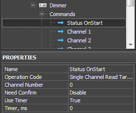
- Operation Code: Single Channel Read Target – the forced request for the dimmer channels brightness
- Channel Number: 0 – indicating zero we request the current state of ALL channels. If you indicate value 1...n you can request the state of some particular dimmer.
- Need Confirm: Disable/Enable - necessity of monitoring the command delivery. It is NOT recommended to use with key modules when working via the Internet (slow connection).
- Use Timer: True - sending the command on timer. The moment of activating the timer is defined by the next string.
- Timer, ms: 0 – the moment of timer activation. In our case it is required to activate the timer only at the project launch and that is why we indicate zero.
This request command is not assigned to graphic items as it is activated only on timer at the project launch without interfering of the graphic interface. The command should be created in the project tree; no more additional actions are required. Dimmer answers will come to the created feedback channels with the Single Channel Control operation code.
![]() For avoiding overload of the bus at the iRidium project launch you can make the request for the state of dimmer channels when opening the page for controlling the relay (sending the request when pressing on the button pf opening the page with graphic items controlling the dimmer and displaying its status). In this case sending on timer should be turned off (Use Timer: False), and assign the command with the help of the Drag&Drop method to the button which opens the required page. When assigning the command select "Send Number", mark the "Press" event, leave the field for inputting values for the "Press" event empty.
For avoiding overload of the bus at the iRidium project launch you can make the request for the state of dimmer channels when opening the page for controlling the relay (sending the request when pressing on the button pf opening the page with graphic items controlling the dimmer and displaying its status). In this case sending on timer should be turned off (Use Timer: False), and assign the command with the help of the Drag&Drop method to the button which opens the required page. When assigning the command select "Send Number", mark the "Press" event, leave the field for inputting values for the "Press" event empty.
Activation of Dimmer Scenes and Sequences
Work with scenes and sequences is set up similarly for all HDL-BUS Pro devices with Scene and Sequence support. You can find information about setting up scenes and sequences in the Scenes and Sequences for HDL-BUS Pro Equipment section.
Relating Dimmer Commands and Channels with Graphic Items
Command sending is activated by the graphic item the command is assigned to. For sending values to the dimmable load channels you can use:
- Level – for regulating the dimmer brightness value in the preset range by moving the Level slider
- Buttons – for sending a particular brightness value. The button stores and sends the selected value to the controlled device address.
- Trigger Button - it switches the brightness between two preset values, for 100% and 0%. The values are indicated in the process of setting up the graphic item. The trigger defines which value will be sent at each pressing depending on the current brightness value received from the feedback channel.
- Up/Down Button – increments or decrements the current value of the dimmer brightness by the preset value. The current value is received from the feedback channel.
Setting Up the Brightness Value by Button
Create a Button type graphic item with 1 or 2 states. With its help you can send one value from the range 0 ~ 100 (% of brightness) to the dimmer channel.
Value selection is made in the process of assigning the command to the graphic item.
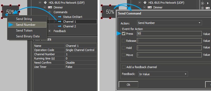
Drag the command from the device tree to iRidium GUI Editor Workspace. When assigning the command to one of the created buttons select Send Number - send the value (constant) to the channel in the window of command assigning:
In the open dialog window indicate the value which is necessary to be sent to the channel and the interface event at which the command for setting the value should be sent:
- Press – the command is sent when pressing on the button
- Release - the command is sent when releasing the button
Such button works without the feedback channel – it does not change the state when the dimmer brightness changes. But pressing on the button is displayed by changing its state and it goes back to the initial state when released. If the button should react on pressings but should not change the state when changing the brightness status, indicate Feedback: Momentary .
The created command is displayed in the Programming tab of the Object Properties window – graphic item settings. If it is necessary the command can be changed from the Press event to Release when dragging it by the text field.
Changing Brightness by Level
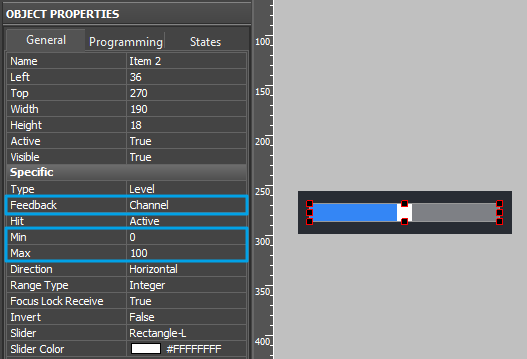
Create a Level type graphic item. With its help you can regulate the brightness value of the dimmable load in the range 0 ~ 100 (% of brightness).
In the graphic item settings indicate the values Min and Max – the lowest and the highest limits of the Level range. For the dimmable load in the HDL-BUS Pro bus the limits are 0 and 100 (it is possible to create a different range but it should be between 0 ~ 100).
Level can change its state when actual values of the dimmable load change. Indicate Feedback: Channel (the item state depends on the feedback channel state) in the graphic item settings.
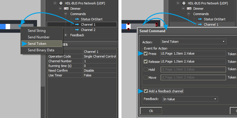
The command is always assigned to Level using the Send Token (send variable value) event as it is required to send the value corresponding to the selected Level scale value in the limits of the range preset at the setting up.
![]() When working with Level it is required to have the feedback channel (activate "Add A Feedback Channel" with channel assigning "In Value"). It is required for the correct initialization of the actual status of the load and displaying it by changing the position of the Level slider.
When working with Level it is required to have the feedback channel (activate "Add A Feedback Channel" with channel assigning "In Value"). It is required for the correct initialization of the actual status of the load and displaying it by changing the position of the Level slider.
The feedback channel can be dragged to the graphic item in the process of working with the command or from the project device tree. At that select "In Value" as the way of assigning.
Switching Two Brightness Values by Trigger Button
Create a Trigger Button type graphic item with 2 states. You will be able to switch two dimmer values in the range 0 ~ 100 (% of brightness), for example:
- 0 – minimum brightness value or
- 100 – maximum brightness value
In the settings of graphic item indicate Trigger Value 1 and 2 – values the trigger will switch at each pressing.
Trigger Button always has 2 states (they are set in the States tab of graphic item properties). State 1 corresponds to Trigger Value 1, State 2 - Trigger Value 2.
In the Trigger Button settings select Feedback:Channel so the trigger could display the actual variable status by changing its state.
The command is assigned to the graphic item using the Send Token event (send variable value), as it is required to send one of the values indicated when setting up the graphic item at each pressing.
![]() When working with Trigger Buttons it is required to have the feedback channel (activate "Add A Feedback Channel" with channel assigning "In Value"). It should be done due to the fact that the trigger selects the next value for sending on the basis of the current relay state and it will not work without the feedback channel!
When working with Trigger Buttons it is required to have the feedback channel (activate "Add A Feedback Channel" with channel assigning "In Value"). It should be done due to the fact that the trigger selects the next value for sending on the basis of the current relay state and it will not work without the feedback channel!
The feedback channel can be dragged to the graphic item in the process of working with the command or from the project device tree. At that select "In Value" as the way of assigning.
Changing Brightness by Up/Down Button
Up/Down Button – it is a button pressing on which sends the task for setting up brightness to the dimmer. The brightness which is sent is higher or lower than the current one by the preset value. The limits and step of brightness change are indicated when setting up the graphic item.
In the item settings indicate the following properties:
- Up/Down Value – the step of brightness increment/decrement, it can be positive or negative.
- Min/Max Value – limits of value change.
For the dimmable load in the HDL-BUS Pro bus the limits are 0 and 100 (it is possible to create a different range but it should be between 0 ~ 100).
To calculate the next value for sending to the bus such button uses the actual brightness value (the feedback channel). But this value should not change the state when the dimmer brightness changes. But pressing on the button is displayed by changing its state and it goes back to the initial state when released. If the button should react on pressings but should not change the state when changing the brightness status, indicate Feedback: Momentary.
The command is assigned to the graphic item using the Send Token event (send the variable value), as it is required to send the value defined by the graphic item as the next one for sending to the bus.
![]() When working with Up/Down Buttons it is ALWAYS required to have the feedback channel (activate "Add A Feedback Channel" with channel assigning "In Value") to calculate values. It is necessary for defining the next brightness value the button should change (on the basis of data about the actual variable state).
When working with Up/Down Buttons it is ALWAYS required to have the feedback channel (activate "Add A Feedback Channel" with channel assigning "In Value") to calculate values. It is necessary for defining the next brightness value the button should change (on the basis of data about the actual variable state).
The feedback channel can be dragged to the graphic item in the process of working with the command or from the project device tree. At that select "In Value" as the way of assigning.
Displaying the Current Value of Brightness
The current brightness value of the dimmable load can be displayed on any graphic item.
Variants of setting up graphic items for displaying dimmer brightness:
- Display Button in which text field there should be indicated the number corresponding to the brightness value and no other symbols
The status channel is assigned to the item by the "In Text" event – it will substitute any text which is in the text field of the item by default. - Display Button in which text field there should be some symbols (measurement units) besides the number corresponding to the brightness value
The feedback channel is assigned by the "In Value"event and indicate the template of value processing - $V in the text field of each graphic item state. The template will be substituted by the value received from the channel at project launch. At that the other text in the item field will not be deleted. - Level which slider will display the brightness value.
The feedback channel is assigned by the "In Value" event. When receiving the value from the channel, the slider will take the position corresponding to the value (in the available range). You can also use the template of value processing - $V with Level. It is added in the text field of both Level states.
Controlling RGB LED Lighting with Color Picker
Control of RGB LED lighting (DMX controller) in the HDL-BUS Pro bus is performed with the help of special module. It converts a color selected from the palette to commands. The commands set up values in three addresses corresponding to the preset values of red, blue and green color of the LED strip light.
Value for the group address controlling the brightness of the LED strip light is sent separately – with the help of Level (not written in script). You can use any type palette as Color Picker.
The distinctive feature of controlling DMX in the HDL-BUS Pro bus is that the value of each color (R,G,B) and Brightness is regulated in the range 0..100 (not 0..255 as it is required for describing each color). Because of this values corresponding to each color should be recalculated from из 0-255 to 0-100.
Creating graphic items for controlling RGB by LED strip light:
- 1. Color Picker – the palette for color selection
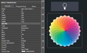
Color Picker – a graphic item with the type "Joystick". In the Image field of the item you should indicate the color palette. The joystick defines the color which should be separated into the colors of the RGB palette under the cursor. At that the joystick cursor can be transparent.
It is important to indicate the range from 0 to 100 for Х and Y coordinates. The settings should be as indicated as for an image.
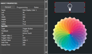
- 2. The item for displaying the color and controlling the brightness
Trigger Button with two states which will switch the LED strip light on/off and display the color under the Color Picker cursor if the LED strip light is activated.
Forming the list of commands for controlling the LED strip light
In the device tree there should be 4 group addresses corresponding to 4 channels for controlling the LED strip light - R (Red), G (Green), B (Blue), Brightness.
They are similar to standard channels for controlling dimmers (see instructions). The commands should be related to the addresses controlling colors of the LED strip light and its brightness.
To define the state of the LED strip light at iRidium launch, create the channel of initial request of DMX channels "Status OnStart" (see instructions).
Adding the Color Picker script in your project
The script for controlling Color Picker should be copied in the Script Editor window of iRidium GUI Editor or imported there as a *.js file.
When creating a new script indicate its name (it should not have numbers only) and add the code for the Color Picker module control:
function work_pick_color(in_color_picker, in_color_resipient, in_sRed, in_sGreen, in_sBlue)
{
   var device = IR.GetDevice("HDL-BUS Pro Network (UDP)");   // HDL Gateway in Project Device Tree
   var color = in_color_picker.PickColor;
   var red = (color  >> 24) & 0xFF;
   var green = (color >> 16) & 0xFF;
   var blue = (color >> 8) & 0xFF;

   in_color_resipient.GetState(1).FillColor = color;

   device.Set(in_sRed, red*(100/255));
   device.Set(in_sGreen, green*(100/255));
   device.Set(in_sBlue, blue*(100/255));
}

// Copy and edit the module to control one more DMX ColourPicker:

IR.AddListener(IR.EVENT_ITEM_RELEASE,
               IR.GetItem("HDL_DMX_Page").GetItem("Item Color Picker 1"),        //  Color Picker (Page.Item)
               function()
               {
                  work_pick_color(
                     IR.GetItem("HDL_DMX_Page").GetItem("Item Color Picker 1"),  //  Color Picker (Page.Item)
                     IR.GetItem("HDL_DMX_Page").GetItem("Item Display Color 1"), //  Display Colour Item (Page.Item)
                     "DMX 1:R",                                                  //  DMX Red Channel (Module.Channel)
                     "DMX 1:G",                                                  //  DMX Green Channel (Module.Channel)
                     "DMX 1:B");                                                 //  DMX Blue Channel (Module.Channel)
               }
               );
Download the file of HDL-BUS Pro Color Picker script
In the script settings (in the lines with the corresponding comments) indicate the following:
- the name of the HDL Network in the device tree of the project to which channels we will send values
- the path to the Color Picker graphic item (RGB palette)
- the path to the graphic item displaying the selected color
- the names of the channels in the project tree (as Device:Channel), where the corresponding colors should be written
Assign the command for regulating the brightness of the LED strip light to the graphic item – Trigger Button. The command is assigned when selecting the "Press" interface event. Also mark "Add a Feedback Channel" in the same dialogue window.
After that the module is fully ready for work.
Download the example of the module for controlling DMX
Sensors, Input/Output Modules, IR Transmitters
When working with different types of sensors different Operation Codes are used. HDL-BUS Pro sensors should be requested about their status as they do not sent data when their status changes. Due to this fact sets of commands and channels are restricted to all types of sensors.
8-in-1 Sensors, Motion Sensors
Download: example of working with an 8-in-1 sensor (project). 0,7 Mb
Operation Code: Sensor 8-in-1 & Motion Read Status, Sensor Lux 8-in-1 Read Status
Parameters for reading: 2 dry contacts (0/1), level of lighting (0/1), motion (0/1),
2 universal  switches(0/1), level of lighting (Lux) – a separate command
Parameters for sending (setting up): IR commands, blocking the motion sensor (lock/unlock)
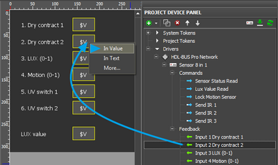
iRidium project requests the sensor status with the preset frequency, on timer (the command in the project tree). Channels of displaying the sensor status are assigned to graphic items:
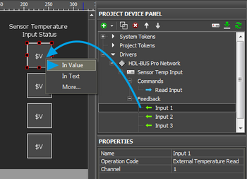
- In Value – when receiving non-zero value from the channel the item takes the active state. This type of assigning enables the change of the item state when changing the channel status. In Value should be selected when using «templates of processing and displaying data»
- In Text – the value received from the channel. It will substitute the text in the item text field.
Parameters of "Sensor Lux 8-in-1 Read Status":
- 1 - Dry Contact 1 (0/1)
- 2 - Dry Contact 2 (0/1)
- 3 - LUX (0/1)
- 4 - Motion (0/1)
- 5 - UV Switch 1 (0/1)
- 6 - UV Switch 2 (0/1)
Parameters of "Sensor Lux 8-in-1 Read Status":
- LUX (Lux)
12-in-1 Sensors
Download: example of working with a 12-in-1 sensor or motion sensor (project). 0,7 Mb
Operation Code: Sensor In One Read Status (for the new sensor firmware),
Sensor 12 in 1 Read Status (for the old sensor firmware)
Parameters for reading: temperature, level of lighting (Lux), presence/motion (0/1),
2 dry contacts (lock/unlock), 2 universal switches (0/1)
Parameters for sending (setting up): IR command
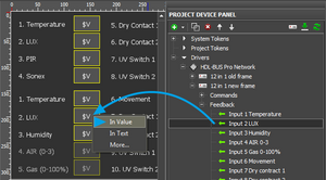
iRidium project requests the sensor status with the preset frequency, on timer (the command in the project tree). Channels of displaying the sensor status are assigned to graphic items:
- In Value – when receiving non-zero value from the channel the item takes the active state. This type of assigning enables the change of the item state when changing the channel status. In Value should be selected when using «templates of processing and displaying data»
- In Text – the value received from the channel. It will substitute the text in the item text field.
If you use a 12-in-1 sensor with old firmware add the ready "Sensor 12-in-1" device from the iRidium database in your project, if you use new firmware – add the "Sensor In One" device from the database in the project.
| assigning channels to graphic items: | "Sensor 12-in-1 Read Status": | "Sensor In One Read Status": |
| 1 - Temperature (-20 ~ 60) 2 - LUX (Lux) |
1 - Temperature (-20 ~ 60) 2 - LUX (Lux) |
Lux&Air, Temp&Lux Sensors
Operation Code: Sensor In One Read Status
Parameters for reading: temperature (value), lighting (Lux), level of humidity (0-100%),
air quality (0-3), motion (0/1), 2 dry contacts, 2 universal switches
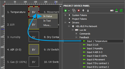
iRidium project requests the sensor status with the preset frequency, on timer (the command in the project tree). Channels of displaying the sensor status are assigned to graphic items:
- In Value – when receiving non-zero value from the channel the item takes the active state. This type of assigning enables the change of the item state when changing the channel status. In Value should be selected when using «templates of processing and displaying data»
- In Text – the value received from the channel. It will substitute the text in the item text field.
The "Sensor In One Read Status" command is universal for "Lux&Air" and "Temp&Lux" sensors but their sets of available parameters are different. If a sensor does not support some parameter it returns 255 in the channel with the parameter which is not supported.
Parameters of "Sensor In One Read Status":
- 1 - Temperature (-20 ~ 60)
- 2 - LUX (Lux)
- 3 - Humidity (0 ~ 100%)
- 4 - AIR (0 ~ 3)
- 5 - GAS (0 ~ 100%)
- 6 - Movement (0/1)
- 7 - Dry Contact 1 (0/1)
- 8 - Dry Contact 2 (0/1)
- 9 - UV Switch 1 (0/1)
- 10 - UV Switch 2 (0/1)
4-contact Module of "Dry Contacts" Inputs
Download: example of working with a module of "Dry Contacts" inputs (project). 0,7 Mb
Operation Code: Sensor Input Read Status
Parameters for reading: state of 4 dry contacts (0/1)
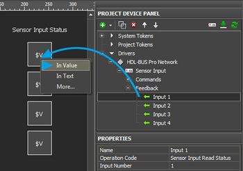
iRidium project requests the sensor status with the preset frequency, on timer (the command in the project tree). Channels of displaying the sensor status are assigned to graphic items:
- In Value – when receiving non-zero value from the channel the item takes the active state. This type of assigning enables the change of the item state when changing the channel status. In Value should be selected when using «templates of processing and displaying data»
- In Text – the value received from the channel. It will substitute the text in the item text field.
Parameters of "Sensor In One Read Status":
- 1 - Input 1 (0/1)
- 2 - Input 2 (0/1)
- 3 - Input 3 (0/1)
- 4 - Input 4 (0/1)
4-contact Module of Connecting Temperature Sensors
Download: example of working with a module of connecting temperature sensors (project). 0,7 Mb
Operation Code: External Temperature Read
Parameters for reading: 4 temperature values (-20 ~ 60 C)
Request of each of the 4 channels of the temperature sensor is performed on timer (all timers are located in the Commands tab and for each of them the frequency of sending requests to sensor inputs is indicated). Timers "Read Temperature 1-4" should not be assigned to commands, they work automatically.
Channels (Feedbacks) should be assigned to graphic items to display the temperature:
- In Value – when receiving non-zero value from the channel the item takes the active state. This type of assigning enables the change of the item state when changing the channel status. In Value should be selected when using «templates of processing and displaying data»
- In Text – the value received from the channel. It will substitute the text in the item text field.
Parameters of "Sensor In One Read Status":
- 1 - Input 1 (-20 ~ 60 C)
- 2 - Input 2 (-20 ~ 60 C)
- 3 - Input 3 (-20 ~ 60 C)
- 4 - Input 4 (-20 ~ 60 C)
IR Transmitters
IR transmitters are not separate devices. They are parts of different HDL-BUS Pro sensors (described above). To send commands written in the sensor memory with the help of IR transmitters use: Operation Code: Universal Control
In the properties of the Universal Control command indicate "Universal Number" – the number of the IR command in the sensor memory.
The command should be assigned to the button with the "Send Number" tag. It is required to send 255 to the sensor so it could send the indicated command.
Floor Heating, Conditioners – Control via DLP-panels or 6-channel Modules
Download: example of working with a DLP-panel. Control of floor heating only(project)
Download: example of working with DLP-panels. Control of air conditioning only (project)
* Download: example of controlling floor heating through the 6-channel module for floor heating
- DLP panels are not used. If one of the module channels is not controlled and returns a non-acceptable temperature value, install v04.16U firmware on the module.
Below, in the instructions the control of air conditioning and floor heating via DLP panels only is described:
Floor Heating
To receive the status of floor heating
use a request with the Floor Heating Read State operation code at the project launch. The request is activated on timer with the preset frequency (for example, once in 10 seconds). It updates the state of floor heating in the project which is particularly important for changing the current floor temperature:
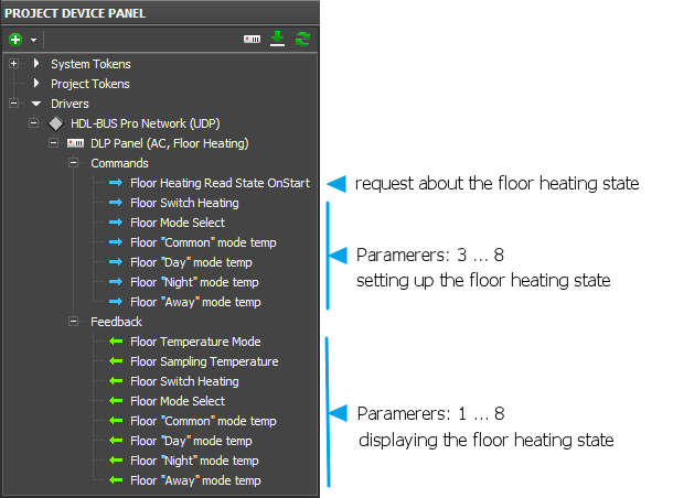
- Parameter 1: Floor Heating Read State - a request for all parameters and operation modes of floor heating.
![]() The request about the status should be in the project but if you have a project with 10-20 devices there can be a necessity of reducing the load which can appear from periodical requests. In this case you should change the request on timer to the request on opening the page. It means you should deactivate the request on timer and assign the commands to the graphic item pressing on which leads you to the page of floor heating control. The command is sent to the item by the "Send Number" event, the value input field should be left empty.
The request about the status should be in the project but if you have a project with 10-20 devices there can be a necessity of reducing the load which can appear from periodical requests. In this case you should change the request on timer to the request on opening the page. It means you should deactivate the request on timer and assign the commands to the graphic item pressing on which leads you to the page of floor heating control. The command is sent to the item by the "Send Number" event, the value input field should be left empty.
To control floor heating
And receive its current operation mode use commands and feedback channels with the Floor Heating Set State operation code and Parameter for setting up different operation modes.
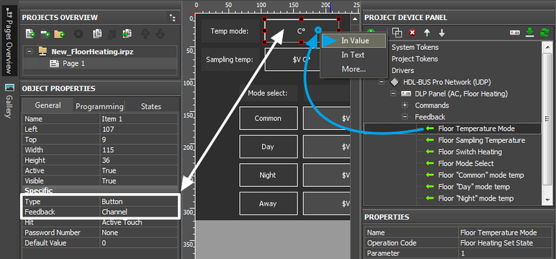
First create feedback channels which will receive the current status of floor heating:
- Parameter 1: Temperature Mode - the mode of displaying the temperature: Celsius or Fahrenheit.
- Parameter 2: Sampling Temperature - the current temperature value of floor heating.
Then create 6 commands and on their basis form feedback channels with the same settings:
- Parameter 3: Floor Heating Switch - turning floor heating on/off
- Parameter 4: Mode Select - selecting the operation mode for floor heating
- Parameter 5: Common mode temperature - selecting temperature value for the «common» mode
- Parameter 6: Day mode temperature - selecting temperature value for the «day» mode
- Parameter 7: Night mode temperature - selecting temperature value for the «night» mode
- Parameter 8: Away mode temperature - selecting temperature value for the «away» mode
It is required to create all the above mentioned commands and feedback channels in the project!
The necessary set of commands for the project looks as follows:
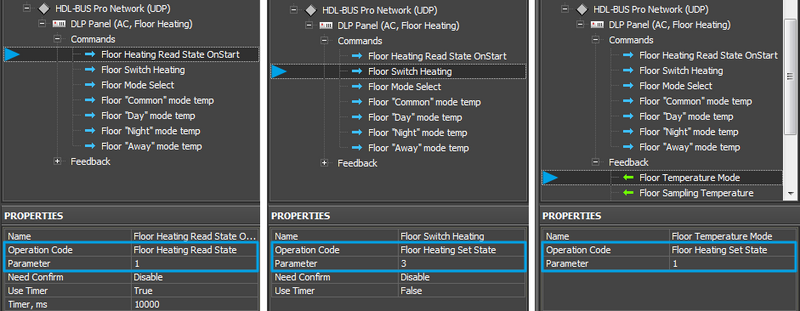
Examples of setting up separate commands from the list of the required:
- Name – the command name, at random
- Operation Code - Floor Heating Set State – for sending and receiving data, Floor Heating Read State – for sending requests about the floor heating state
- Parameter: 1 ... 8 – one of the 8 parameters of floor heating
- Need Confirm: Disable/Enable – necessity of monitoring the command delivery. It is NOT recommended to use with key modules when working via the Internet (slow connection).
- Use Timer: False/True – sending the command in cycles, on timer. It is used only for sending requests about the floor heating state (Floor Heating Read State).
The commands can be used with different types of graphic items. For controlling bit variables (1/0) and sending fixed values you can use Button and Trigger Button. For controlling variables in a bigger range you can use Level, Up/Down Button, etc.
Floor Switch Heating (Parameter: 3) – turning floor heating on/off
You can turn floor heating on/off with the help of Trigger Button or two Buttons:
- Button can send one value – turn on (1) or off (0). The command is assigned with the "Send Number"tag. In the input field indicate the number which has to be sent (1 or 0) and sending event (pressing on the button or releasing it)
- Trigger Button – switch two values. The command is assigned with the "Send Token" tag. Leave the input field by default, select the sending event (pressing on the button or releasing it). For Trigger Button activate "Add a feedback Channel", as the trigger selects the value for sending on the basis of the current variable value.
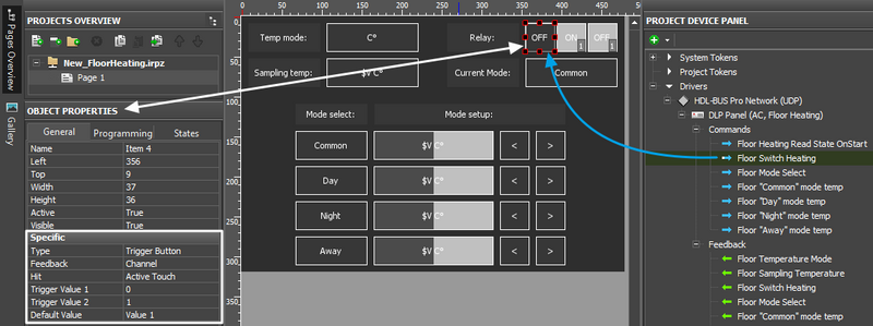
Example (Trigger Button):
Set up the item and assign the Floor Switch Heating command to it:
When assigning the command select the "Send Token" tag (it is always used for triggers as it allows to receive value from the graphic item), activate "Add a feedback Channel".
After that the trigger is ready for work – it can turn floor heating on and off.
Floor Mode Select (Parameter: 4) – select the operation mode of floor heating
You can select the operation mode of floor heating with the help of (Floor Switch Heating a set of Trigger Buttons (it allows you to set up the mode and display the current active mode on the same items) or a set of Buttons (it allows you to set up the mode, but you cannot display it on the buttons).
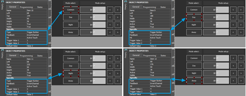
- 4 Trigger Buttons – they will work as Radio Buttons: when only one of the buttons from the group can be "active" (pressed). This principle is used for displaying the selected operation mode of floor heating and requires special setting up.
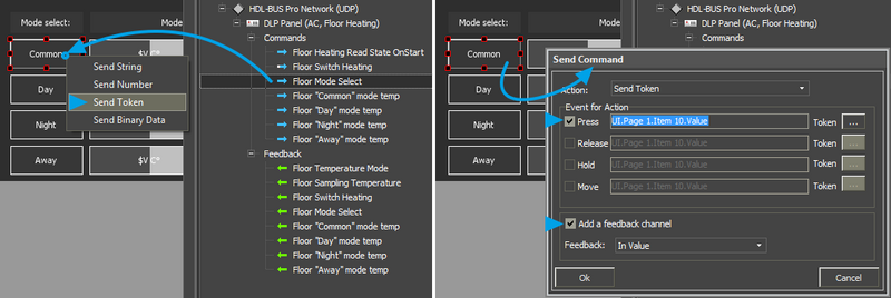
- 4 Buttons - they will send values corresponding to the operation modes of floor heating: Common (1), Day (2), Night (3), Away (4). The Floor Mode Select command is assigned to the buttons with the "Send Number" tag. In the input field indicate 1, 2, 3 or 4 depending on the mode the button has to activate.
Example (4 Trigger Buttons):
Set up graphic items so each of them could send the same value on pressing (Trigger Value 1 = Trigger Value 2) corresponding to the operation modes of floor heating: Common (1), Day (2), Night (3), Away (4).
Indicate "Feedback: InvertChannel" for the graphic item. At that the trigger will take the active (second) state when receiving the value corresponding to the one in its settings:
Assign the Floor Switch Heating command for each trigger selecting the "Send Token" tag. Activate "Add a feedback Channel" as triggers have to display the current operation mode of floor heating:
After that the set up triggers can activate the operation modes of floor heating and display the current operation mode by their active state (State 2).
Display the operation mode of floor heating (example):
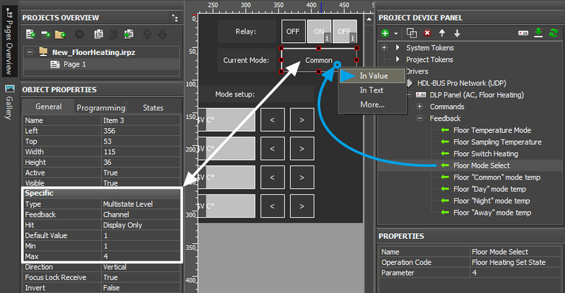
Irrespective to the set of items you control the operation mode of floor heating, you can display the current operation mode on Multistate Level graphic item. This item is used as you can create several states and open any of them when receiving a particular value from the equipment. Each state of Multistate Level corresponds to the value of the item scale which range can be indicated at random.
Create Multistate Level with 4 states and the Min/Max range: 1/4. In the text field of each state indicate the corresponding mode - Common (1), Day (2), Night (3), Away (4). Assign the feedback channel to the item to receive information about the operation mode of floor heating (Parameter: 4).
The created graphic item will display the current operation mode of floor heating.
Common, Day, Night, Away Mode Temperature (Parameter: 5-8) – set up temperature for the particular mode
To set up temperature for each operation mode of floor heating use Button (fixed value), Level (regulating value in the preset range by the slider), Up/Down Buttons (increment/decrement the current value at each pressing).
Temperature of floor heating in any mode is regulated in the range from 5 to 35 degrees. No other values can be set up.
Example (Level and Up/Down Buttons):
Set up two types of graphic items for controlling temperature – Level and Up/Down Button. For Level the required properties – the regulation range (Min...Max: 5...35). For Up/Down Buttons indicate: Up/Down Value – the step of temperature change at each pressing (incrementing or decrementing the current value), Min/Max Value – limits of incrementing/decrementing (minimum – for decrementing, maximum – for incrementing).
To all created items assign the "Set Mode Temperature" command with the "Send Token" tag. Leave the input field by default, select the sending event (pressing on the button or releasing it). Activate "Add a feedback Channel" for all items:
Temperature Mode (Parameter: 1) и Sampling Temperature (Parameter: 2)
- temperature measurement units, the current temperature of floor heating
Parameters 1 and 2 for working with floor heating cannot be set up but can be received and displayed in the project. They are temperature measurement units (Celsius or Fahrenheit) and the current temperature of floor heating.
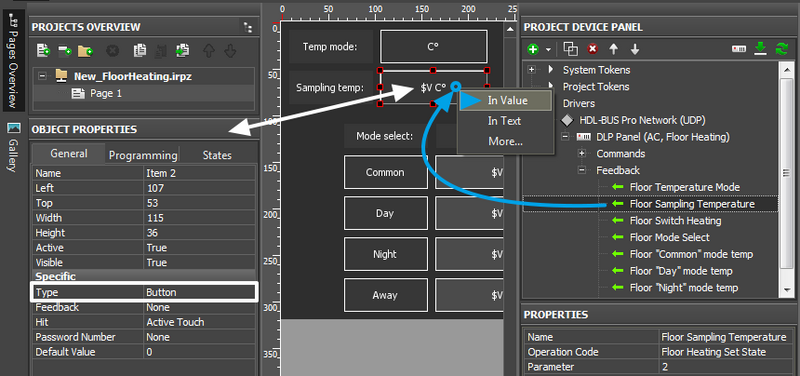
To display the values in iRidium projects you can use display buttons (1 state) or buttons changing their state and thus displaying the current variable status.
Example (display button)
Create Button with 1 state and indicate «template of processing values and displaying then on graphic items », $V, which allows to display the value from the channel and add measurement units or text to it:
Example (button with 2 states)
Create Button with 2 states. In the text field of the first state (Object Properties > States > Text) indicate "С" (Celsius), in the second - "F" (Fahrenheit). Feedback type for Button - Feedback: Channel.
Conditioners
To control conditioners
Use commands with the Panel Control operation mode:
| Parameter | Description | Regulation range |
| 3 | AC power. Turning the conditioner on/off | 0: off ; 1: on |
| 4 | Cooling Temp. Temperature in the Cooling mode | 0 ~ 84 |
| 5 | Fan speed. Selecting the operation mode of the fan | 0: Auto; 1: High; 2: Medium; 3: Low |
| 6 | AC Mode. Selecting the operation mode of the conditioner | 0: Сooling; 1: Heating; 2: Fan; 3: Auto; Dehumidify |
| 7 | Heating Temp. Temperature in the Heating mode | 0 ~ 84 |
| 8 | Auto Temp. Temperature in the Auto mode | 0 ~ 84 |
| 9 | Rise Temp. Increase the temperature | 0 ~ 10 |
| 10 | Decrease temp. Decrease the temperature | 0 ~ 10 |
| 12 | AC Lock. Block the control | 0: off; 1: on |
To display the conditioner status
Feedback channels are created on the basis of commands controlling the conditioner. They can be created in the process of assigning commands to graphic items or on the basis of commands with the help of the "Create Feedbacks" command in the right-click menu.
To receive the conditioner status at the project launch
It is required to create requests – the duplicates of commands for controlling the conditioner – with the Panel Read Status operation code and the timer activated at the project launch.The set of requests will use the same Parameters, but these commands will be sent once at the iRidium project launch.
![]() The request about the status should be in the project but if you have a project with 10-20 devices there can be a necessity of reducing the load which can appear from periodical requests. In this case you should change the request on timer to the request on opening the page. It means you should deactivate the request on timer and assign the commands to the graphic item pressing on which leads you to the page of conditioner control. The command is sent to the item by the "Send Number" event, the value input field should be left empty.
The request about the status should be in the project but if you have a project with 10-20 devices there can be a necessity of reducing the load which can appear from periodical requests. In this case you should change the request on timer to the request on opening the page. It means you should deactivate the request on timer and assign the commands to the graphic item pressing on which leads you to the page of conditioner control. The command is sent to the item by the "Send Number" event, the value input field should be left empty.
AC power. Turning conditioner on/off
To turn the conditioner on/off use Trigger Button or two Buttons:
- Button can send one value – turn the conditioner on (1) or off (0). The command is sent to the item by the "Send Number" event. Indicate the number which should be sent (1 or 0) and sending event (pressing on the button or releasing it) in the input field.
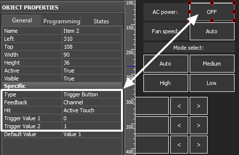
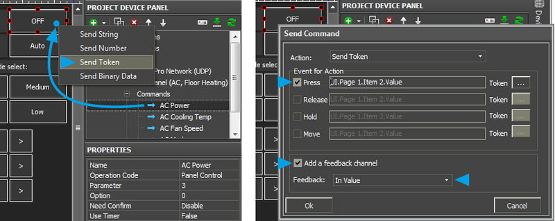
- Trigger Button – switch two values. The command is assigned with the "Send Token" tag. Leave the input field by default, select the sending event (pressing on the button or releasing it). For Trigger Button activate "Add a feedback Channel", as the trigger selects the value for sending on the basis of the current variable value.
Example (Trigger Button):
Set up the trigger. Select which values it will switch - 1 and 0:
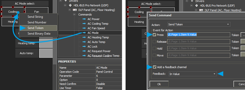
Assign the AC power command to Trigger Button Перетаскиваем на триггер команду AC power. When assigning the command select the "Send Token" tag (it is always used for triggers as it allows to receive value from the graphic item), activate "Add a feedback Channel".
After that the trigger is ready for turning the conditioner on and off.
AC Mode, AC Fan Speed. Selecting the operation mode of the conditioner and fan
There are 4 operation modes of the conditioner (0: Auto; 1: High; 2: Medium; 3: Low) and 4 operation modes of the fan (0: Сooling; 1: Heating; 2: Fan; 3: Auto; Dehumidify) switching of which can be set up in iRidium. You can select from 2 variants:
- Buttons - create 4 buttons for sending commands of activating the modes. The buttons are linked with one command in the project tree (AC Mode or AC Fan Speed), value selection is made at the assigning of the command to the graphic items with the "Send Number" tag. It is possible to display the current mode only on a separate item.
- Trigger Buttons - create 4 triggers. Triggers can set up and display the operation mode of the conditioner of fan which cannot be done by Buttons to the full extent.
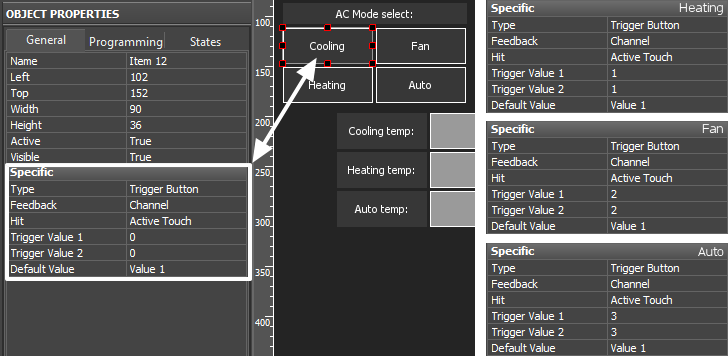
Example (switching conditioner modes, triggers)
In this case triggers are not set up in a standard way as they can store only two values and we need to regulate values in the range 0~3. Using of triggers makes it possible to display the current operation mode of the conditioner. Three items are set up as "Radio Buttons" – when activating one of the buttons from the group the other buttons are deactivated automatically.
Create 4 Trigger Buttons with 2 states.
Indicate the following properties:
- for the Auto button - Trigger Value 1 and 2: 0 and 0, Feedback: Invert Channel
- for the High button - Trigger Value 1 and 2: 1 and 1, Feedback: Invert Channel
- for the Medium button - Trigger Value 1 and 2: 2 and 2, Feedback: Invert Channel
- for the Low button - Trigger Value 1 and 2: 3 and 3, Feedback: Invert Channel
Trigger Button always has 2 states (they are set in the States tab of graphic item properties). State 1 corresponds to Trigger Value 1, State 2 - Trigger Value 2. When setting up similar values the trigger will send the same value at each pressing but will become active (change to the second state) only if it receives the value corresponding to the lower value. Thus the trigger will be active only until it receives the value which equals to Trigger Value 1. It allows you to monitor the status of the conditioner of fan.
The command is assigned to the graphic item using the Send Token event, as it is required to send one of the values indicated when setting up the graphic item at each pressing.
![]() When working with Trigger Buttons it is required to have the feedback channel (activate "Add A Feedback Channel" with channel assigning "In Value") to display the current operation mode of the conditioner or fan.
When working with Trigger Buttons it is required to have the feedback channel (activate "Add A Feedback Channel" with channel assigning "In Value") to display the current operation mode of the conditioner or fan.
The feedback channel can be dragged to the graphic item in the process of working with the command or from the project device tree. At that select "In Value" as the way of assigning.
AC Cooling, Heating, Auto Temp – setting up temperature for different modes.
There are 3 operation modes of the conditioner (Cooling, Heating, Auto). You can set up the temperature value the conditioner will take for each mode.
To set up temperature for each mode use Button (fixed value), Level (regulating value in the preset range by the slider), Up/Down Buttons (increment/decrement the current value at each pressing).
Temperature in any mode is regulated in the range from 0 to 30 degrees. No other values can be set up.
Example (Level and Up/Down Buttons):
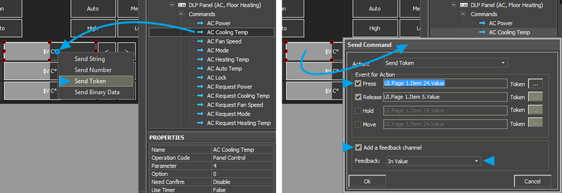
Set up two types of graphic items for controlling temperature – Level and Up/Down Button. For Level the required properties – the regulation range (Min...Max: 5...35). For Up/Down Buttons indicate: Up/Down Value – the step of temperature change at each pressing (incrementing or decrementing the current value), Min/Max Value – limits of incrementing/decrementing (minimum – for decrementing, maximum – for incrementing).
To all created items assign the "Set Mode Temperature" command with the "Send Token" tag. Leave the input field by default, select the sending event (pressing on the button or releasing it). Activate "Add a feedback Channel" for all items:
Power Meters
Download: example of receiving data from a power meter (project). 0,7 Mb
In iRidium you can output data from HDL Power Meter. Data output can be used for monitoring real-time power consumption of the whole automation object.
Parameters available for reading (request to each parameter is made forcedly with the selected frequency) are the following:
- Voltage RMS – current voltage (A:1, B:2, C:3)
- Current RMS – current AC value (A:1, B:2, C:3, T:4)
- Active Power – active power (A:1, B:2, C:3, T:4)
- Power Factor – power factor (A:1, B:2, C:3, T:4)
- Active Energy – active energy (A:1, B:2, C:3, T:4)
- Frequency – network frequency
Each parameter of the power meter is requested separately with the help of the command in the project device tree which uses the timer. The received data are output in the feedback channels.
Request commands are created for each power meter parameter. For each command indicate Parameter: 0 – request the selected parameter in all phases; activate the timer for sending cyclic requests to the parameter. It is not recommended to send requests to the power meter more frequent than once in 5 seconds (5000 ms). In feedback channels indicate Parameter: 1...4 – the number of the phase which requested parameter value it is required to output.
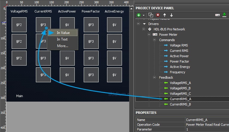
The parameter state of the power meter can be output on any graphic item. It is more convenient to use a display button with 1 state:
- For the display button in which text field there should be output the number without measurement units, the feedback channel is assigned by the "In Text" event – it will substitute any text which is in the text field of the item with the value from the channel.
- For the display button in which text field there should be some symbols (measurement units) besides the value from the channel, the feedback channel is assigned by the "In Value"event. In the text field indicate the template of value processing :
- $F3 – to output values from the channel to the third decimal place
- $F2 – to output values from the channel to the second decimal place
- $V – to output whole values from the channel
You can indicate any text or measurement units before or after the template – only the template can be changes by the value from the channel.
Security Modules
Download: example of controlling a security module (project). 0,7 Mb
Operation codes: Security Arming Read Status, Security Arming Control, Security Alarm Control
Before starting work add iRidium control panels in the list of devices which can control
the security module. "Subnet ID/Device ID" iRidium: 253/254
Security modules have two sets of commands: Arming – setting up (reading) the security mode and Alarm – activation of one of the security modes. Only one security mode (Arming) can be active at a time but you can activate several events of the security module (Alarm).
The "Security Arming Read Status" command works without assigning to graphic items. It is activated only at the project launch to initiate the security module state. In order to do that activate the timer with the value "Timer, ms: 0" in the command settings.
Arming
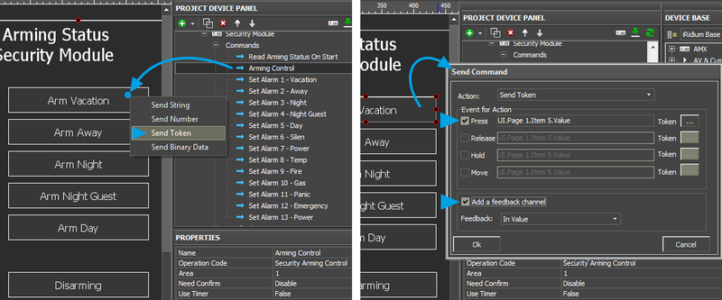
Security Arming Control – the command of setting up (and displaying) the current security mode. There are 6 modes:
1 - Vacation, 2 - Away, 3 - Night, 4 - Night Guest, 5 - Day, 6 - Disarm.
Only one security mode (Arming) can be activated at a time. Activation of a new security mode turns off the previous one. That is why there is one command for Arming. The Arming operation mode is set up by Value inside the channel.
When launching iRidium projects the current Arming mode is requested with the help of the Security Arming Read Status command. Further on the module informs about changing its module automatically.
For convenience of switching the modes it is recommended to use a set of Trigger Buttons which are set up as Radio Button – when activation of one Trigger Button from the group automatically deactivates the other ones:
Set up 6 triggers for controlling Arming modes. The highest and the lowest trigger limits are equal to each other. It enables sending of the same value at each pressing. At that due to "Feedback: InvertChannel" the trigger will take the active state only when the value in it equals to the second preset value.
Assign the command of event activation to the triggers using the "Send Token" tag, activate "Add a Feedback Channel".
Also assign the command to 6 buttons for controlling the security modes and the buttons are ready for work. If you do not need all security modes you can skip them.
Alarm
Security Alarm Control - the command for activation of the event on which the module gives a particular reaction. You can activate several events at a time. You can also receive data about the events which are active at the moment.In order to do that use a set of commands which store data about what event is active and what zone it is active in.
There are 13 events:
1 - Vacation, 2 - Away, 3 - Night, 4 - Night Guest, 5 - Day, 6 - Silen,
7 - Power, 8 - Temp, 9 - Fire, 10 - Gas, 11 - Panic, 12 - Emergency, 13 - Power
To activate/deactivate any event use Trigger Button with the following settings:
Assign the command of event activation to the triggers using the "Send Token" tag, activate "Add a Feedback Channel":
After that the button will activate or deactivate the event depending on its current state at each pressing.
Scenes and Sequences for Different Equipment
Example of launching sequences and scenes for relays
Scenes and Sequences can be set up for many devices in the HDL-BUS Pro bus. They work similarly. The command of activating a scene or sequence can be created even if you do not have it in the preset device it is required to control:
In the settings of the scene or sequence indicate "Area" – the zone it is saved for. The scene number is indicated when assigning the command to the graphic item - Button:
Here the outgoing Value: 2 is the number of the scene or sequence it is required to activate.
You can request the number of the active scene /sequence at the project launch with the help of the command Scene Read Status / Sequence Read Status. It can be activated on timer at the project launch:
Do NOT assign the command with timer to graphic items. It will be activated automatically at the launch of the iRidium project on your control panel. The command will return the number of the scene/sequence which is active at the moment in Area (zone).
SMS Modules with Ethernet Interfaces
In iRidium SMS modules belong to the type of universal devices Logic (universal). The devices are controlled by the Universal Switch command which enables sending of the SMS message which was formed in the module memory.
The message sending is performed with the help of Universal Switch command. Indicate Universal Number – the SMS number in the module memory – in the settings. When assigning the command to the button indicate Value:255 – send the SMS.
Gateways and Bridges for Integration with Third-party Equipment
Gateways and bridges for integration of HDL-BUS Pro bus with device working via RS232/485, IP/UDP, KNX/EIB and etc. store commands to third-party equipment in their memory and enable exchanging data with the equipment. In iRidium these devices belong to the type of universal devices Logic (universal). The devices are controlled by the Universal Switch command.
With the help of the Universal Switch command you can send commands which were formed in the module memory. Indicate Universal Number – the command in the gateway memory. When assigning the command to the button indicate Value:255 – send the command.
Logic Controllers
A number of logic variables (Universal Switch) are formed when setting up of the logic controller. You can control the variables (False/True) or just receive their status. In iRidium logic controllers belong to the type of universal devices Logic (universal). The devices support the Universal Switch/ Universal Read Status commands.
When setting up the Universal Switch command indicate Universal Number – the address of the logic variable in the module memory. When assigning the command to the button indicate Value: 255 - True, Value: 0 - False.
Universal Read Status works by the forced request. So create a request command which is launched on timer and a feedback channel to display the variable status.
The request command is not assigned to graphic items. It is performed automatically with the preset frequency. The feedback channel should be assigned to the displaying graphic item.
How to Decrease Load on HDL Equipment When Requesting States of Variables
To get the initial state of the bus variables, the i2 Control V2.2 application sends requests at launch. In response to the requests the bus devices send their states. There are also devices in the HDL bus which do not send its changed status without the forced request (different sensors, including the temperature sensor).
Thus, a lot of bus devices require frequent requests which can be excessive for normal work of the bus. It can surface as partial loss of feedback, loss of command delivery to equipment.
Optimization of iRidium projects – decrease of maximum load on the bus (the number of simultaneous, including cyclic, requests).
- 1. Requests for states is performed at launch of iRidium projects (Timer: 0), so the maximum load falls on the launch or reconnection of the iRidium client to the bus. The effective way of decreasing the maximum load is cancelling requests of some or all bus devices at the project launch (as often all statuses are not required at launch).
- 2. Change of the way the status of devices is requested. Earlier requests for the status of all devices were sent at the project launch disregarding the fact that the data about the devices are not displayed on the start page. Now requests will be sent when opening pages with the items related to the devices the status of which are being requested.
When scanning the HDL-BUS Pro network the channels requesting the variable states have a preset property «Timer: True (Timer: 0)» - to request data when connecting the client to the bus. Change the command setting to «Timer: False» and assign the command to the button which opens the page (Event: Press or Release).
Setting up requests way, you will considerably decrease the request frequency of the HDL but and will avoid its overload.
Besides, you have to consider the following recommendations on project setting:
- When possible, decrease the number of group requests for the variable states. If it is required to display the states of several device outputs, there is no point in requesting the states of all its outputs (especially when the device has a considerable number of outputs). Create separate requests for the state of each output.
- Request the variable states when opening the page with the data of the requested device to decrease the load on the bus.
- If the cyclic request of the device is required (for example, to receive temperature or the dynamic status), try to make the request cycle as long as possible. Request of any variable should not be more often that once in 1-2 seconds. Temperature has to be requested not more often that once in 10-20 seconds.
- If after scanning of the HDL bus you formed the list of devices but some of them are not used (you don’t need to control them or receive their status) – remove the unused devices from your iRidium project.
- if you need to control 4 out of 8 equipment channels in your iRidium project, remove the unused channels (if you are sure they won’t be used). In general, it concerns the channels for which the initial or constant requests are set up.
