Setting up АМХ Commands in iRidium GUI Editor
In order to create a project for controlling AMX in iRidium GUI Editor it is necessary to know principles of its work. The main stages of working with projects, setting up of graphics and licensing are described in the article:
Start Your Work with iRidium
After reading the article "Start Your Work with iRidium" you will be able to create the project graphic part (visualization) and receive your iRidium license. Then you can proceed with setting up AMX control in the project.
Variants of creating projects for АМХ using iRidium GUI Editor:
| Edit *.TP4 projects Projects created in TPDesign4 can be opened and edited in GUI Editor |
Use templates On the iRidium mobile web site you can buy or download free ready graphic interfaces for their use in your future projects. |
Create your own projects You can create your own unique GUIs using your own images added in GUI Editor Gallery. |
What are advantages of GUI Editor in comparison with TPDesign4? Why might you need those features?:
- GUI Editor does not limit users in the choice of the panel resolutions. When you work in TPDesign4, you cannot select the resolution manually (for example, to create your widget or a project for TV). It also does not create projects with resolution more than 2000px.
- iRidium GUI Editor has more visualization tools. The most popular among them is "Static List" which allows to scroll popups of your project similarly to the iPad or iPhone desktop.
There is also a unique item "List", which supports commands from the АМХ controller (it can be created in TPDesign4, but it will work only on iRidium panels). - In iRidium GUI Editor you can set up connection of the visualization project to SEVERAL AMX controllers at a time! The project will support simultaneous connection sessions.
- The part of the code can be stored directly on control panels. The iRidium Script language (on the basis of Java Script) is used for that. With the help of iRidium Script you can activate commands to the АМХ controller, listen to the data coming from the controller and based on that activate any commands to the controller and GUI interface.
- Besides controlling АМХ, you can control any iRidium supported equipment in the same project, including Audio/Video equipment, media servers, etc. It is very convenient when you need to control several systems.
Other advantages of using iRidium for AMX and iRidium GUI Editor are described in the description of the iRidium for AMX product.
Contents
Properties of the АМХ Driver in iRidium GUI Editor
If you plan to edit your ready *.TP4 project in iRdium GUI Editor and change the graphic part of the project, use information about graphic capabilities of GUI Editor:
iRidium GUI Editor
If you plan to create a graphic part of the project from scratch, on the basis of your own design or using templates, you will need information about setting up the AMX driver in iRidium GUI Editor presented below.
Add the driver for connecting to AMX
Create a new project in iRidium GUI Editor or open your ready interface on which basis you will create the АМХ control project in GUI Editor.
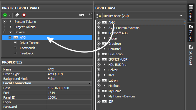
Open the panels DEVICE BASE and PROJECT DEVICE PANEL in GUI Editor. The first panel stores all iRidium supported drivers, the second stores the drivers that will be used in your projects.
Add the АМХ driver from the base. It can be done by dragging it in PROJECT DEVICE PANEL.
Set up properties of connection to AMX in the PROPERTIES tab of PROJECT DEVICE PANEL:
| Properties of connection to АМХ | |
| Host | the IP-address of the АМХ controller |
| Port | the control TCP port (it is always 1319) |
| Panel ID | the unique panel identifier (Panel ID). It should not be the same on different panels. It is set on the controller when creating the list of panels which can connect to АМХ. |
| Login | the login when using the secure connection |
| Password | the password when using the secure connection |
For the variant of creating the АМХ driver with the list of commands and channels for it: import them from the ready *.TP4 project if you need its graphic part. For the import open the menu File > Import > and indicate the path to the project where you want to import the drivers from.
- Unlike in TPDesign4 commands and channels for AMX in iRidium GUI Editor are not initially assigned to graphic items. To relate a project graphic item with the AMX address or channel you need to drag the AMX command on the graphic item. At that the command or channel should be created in the project in advance (PROJECT DEVICE PANEL).
Set up communication with АМХ
The PROJECT DEVICE PANEL tree contains several tabs each of which can be used when controlling АМХ or setting up visualization. The principle of working with commands and channels is different from the one of TPDesign4. When setting up the АМХ driver you will see:
Driver tokens
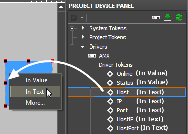
- variables which return the state of connection to АМХ. These properties can be read only. To use a token drag it on the graphic item (the token value can be output in the item text field or used for changing the item state)
| Online | the state of connection to АМХ (Online/Offline = 1/0) |
| Status | the status of connection to АМХ (Offline/Connect/Online/Disconnect = 0...3) |
| Host | the domain name of the remote system |
| HostPort | the port on the remote system which iRidium connects to |
| IP | the IP-address of the control panel |
| HostIP | the IP-address of the remote system which iRidium is connected to |
| Port | the local iRidium port used for connection with АМХ |
- There are no tools similar to Project Tokens or System Tokens in AMX TPDesign4. Using System Tokens you can receive date, time and other parameters of the panel with running iRidium
Commands -
are used for sending data to a particular port and code.
Commands can be of different types:
- Command – sending an АМХ command
- String – sending a string
- Channel – channel activation
- Level - sending Level
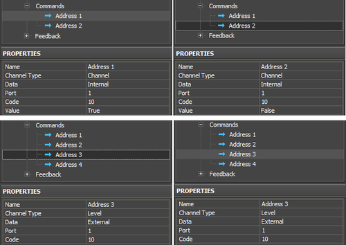
- A command can store data for sending (Level, string, command) inside itself (Data: Internal) or receive the value or command from a graphic item (Data: External).
The External value is indicated when dragging the command on the graphic item. The Internal value is stored in the Value string of the command settings.
Feedbacks (feedback channels) -
are used for receiving data from АМХ.
Channels can be of different types:
- Address – the address variable receives commands from АМХ. The commands can affect any property of the graphic item.
- Channel – the True/False trigger
- Level - the value from the range
- A feedback channel is assigned to a graphic item – Button or Level. If the channel has the Channel or Level type is will receive a number. The channel with the Address type can receive command for changing any property of the graphic item to which the channels is assigned.
Controlling АМХ Channels
In order to activate a channel, send Level, a string or an АМХ command, it is required to create the commands in the iRidium project tree and assign them to graphic items. There are different variants of setting up and sending commands of different types.
Send Channel
Channel – it is an АМХ channel which can send True/False values and thus inform about pressing/releasing the item with the corresponding address.
The channel is activated at pressing (PUSH > True) and clears at release (RELEASE > False). You need to set up the same behavior for the channel in iRidium.
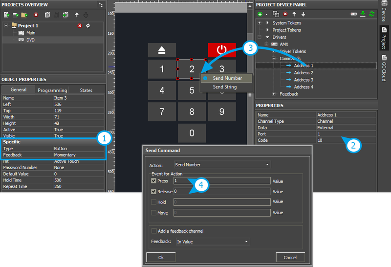
Create a command and assign it to Button:
- Set up Button (Type: Button, Feedback: Momentary)
- Set up the command in PROJECT DEVICE PANEL. The command has the Channel type with the External data source – the value for sending is indicated in the properties of the assigned Button
- Drag the command from the tree on Button and select Send Number – send the number to the channel
- Activate the Press and Release events (events at which the command is activated), in the Value field for the events indicate Press: 1, Release: 0, which corresponds to the values True/False.
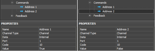
The second variant of implementing the same event (Channel True/False) – using Data: Internal, when the values (1\0) are indicated in the Value command property and not when dragging commands on the item:
When using Data: Internal, the commands should be assigned to Button, Value: False – to the event Press, Value: True – to the event Release, but do not indicate Value in the dialog window. The system will work similarly but there will be 2 times more commands in the project tree window and that is not convenient.
iRidium development tools are oriented to the use External Data (when the value for sending is indicated directly for the graphic item and it is not stored inside the command.
Send Level
Level – it is an АМХ channel, which can send values in some particular range (usually Unsigned 16-bit). It is used in АМХ for controlling values by the slider.
In АМХ the value to Level is sent at the events: PUSH, MOVE, RELEASE. In iRidium you can activate the same events or just use PUSH and RELEASE (at option).
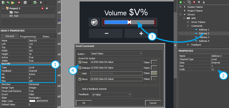
Set up Level, indicate the value regulation range and assign the command to it:
- Set up Level (Type: Level, Feedback: Channel)
- Set up the command in PROJECT DEVICE PANEL. The command has the Level type with the External data source – the value for sending is indicated in the Level
- Drag the command from the tree on Level. It will automatically select Send Token – it means that the value sent to Level will depend on the slider position.
- Activate the Press and Release, Move events (events at which the value has to be sent to AMX).
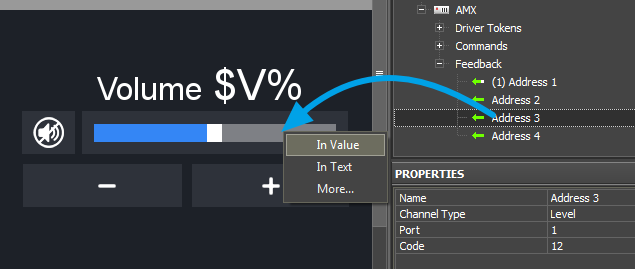
- To display the current variable state Level needs a feedback channel. It is set up similarly to the initial command and is assigned to Level [In Value]
As in the case with Channel, you can use Internal Data for Level type commands. But you will not be able to assign such commands to Level. They can be used with Buttons only for sending constant values.
Besides Level you can use other items for controlling values in iRidium:
- Trigger Button – it switches two constant values. This item requires feedback about the address state.
- Up/Down Button – it increment/decrements the current value of the address by the preset amount depending on the current address state.
Trigger Button and UP/Down Buttons stores values for sending in their properties. Commands and feedback channels are assigned to them as to Level.
Send Command, Sens String
Sending commands and strings to the address is performed similarly. You can indicate data for sending both inside commands (Internal Data) and when dragging them on items (External Data).
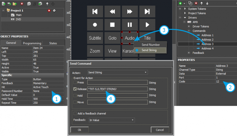
You can send a command/string at the PUSH or RELEASE event:
- Set up Button (Type: Button, Feedback: Momentary)
- Set up the command in PROJECT DEVICE PANEL. The command has the Command (String) type with the External data source – the value for sending is indicated in the properties of the assigned Button
- Drag the command from the tree on Button and select Send String – send the string to the address
- Activate the Press and Release events (events at which the command is activated), in the Value field select the string for sending.
Receiving Data from АМХ
You can change the state of Button, Level or other graphic items in the project by the command from the AMX controller. It can be performed by several ways:
- Address – the feedback channel which can send commands for changing properties of the graphic item from the controller. If you assign such channel to Button then you will be able to change any property of this Button by commands from the controller.
- Channel – the feedback channel which sends True/False values. It is used for changing the Button state from State 1 to State 2 and back.
- Level – the channel sending values in the range of Unsigned 16-bit (other data size is not usually used). It is used for displaying the current variable value in some particular range (for Levels, Trigger Buttons, Up/Down Buttons)
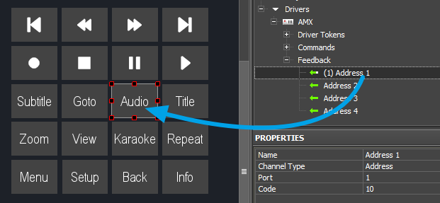
To change Button properties by the Address channel create the channel in the Feedbacks tab of the АМХ driver, indicate its Port and Code, assign the channel to Button and assign the channel to Button:
Now you can change any property of the selected graphic item by sending command to the selected Port/Code.
To use the Channel and Level channels create them in the Feedbacks tab of the АМХ driver indicate Port and Code of the channels and assign channels to the corresponding items:
Feedback channels are assigned to graphic items with indication of what particular properties of the graphic items will be affected by the value received from the channel. Thus such channels will affect particular item properties (Item.Value, Item.Text, etc.):
- In Value – values received from the feedback channel will change the graphic item from the active state to inactive and back or will move the slider. It is also used for working with «templates of data processing and output» (see below)
- In Text – values received from the feedback channel will substitute any text written in the item test field by default
- More... – here you can select any graphic item property which you want oto be affected by the value from the channel, for example, opacity, activity, X and Y coordinates, etc.
Template |
Function |
Template |
Function |
$P |
Output of the current level value in percentage | $V |
Output of the current value |
$L |
Output of the lower level value | $H |
Output of the upper level value |
$S |
Output of the current state number | $A |
Output of the current value minus the lower level value |
$R |
Output of the level range (Upper level value minus lower level value) | $F1-5 |
Output of the value with a floating point, number of symbols after a point |
$X |
Output of the current value in the hex type | $$ |
Output of the "dollar" symbol |
A command (template) of incoming data processing and displaying is entered into the text field of a graphic item and can be combined with other text or symbols (comments, units of measurement)
Working with Scripts
In the iRidium for АМХ project you will be able to set up scripts which enable to change the interface features without using the controller. Scripts can also help you to create scenes, requests to AMX and separate drivers for controlling Audio/Video equipment.
There are a few ready modules for Audio/Video equipment and enhancing the interface control in iRidium. You can find more information about scripts here:
