AV & Custom Systems: Control via TCP
<< back (AV & Custom Systems: Working with Equipment via TCP)
This article presents control of AV equipment or other systems via TCP through the example of the Kramer device with protocol 3000.
Contents
Principles of Controlling Equipment via TCP
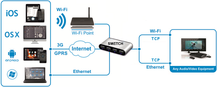
To control Smart Home systems via TCP commands (Ethernet or Wi-Fi) iRidium uses the freely customizable "AV & Custom Systems" (TCP) which enables iRidium to send commands via TCP. Thus the scheme of communication between an iRidium control panel and controlled equipment looks as follows:
Commands can be sent to TCP devices in the ASCII, HEX or DEC formats. When sending commands use special iRidium syntax to define the data format.
Adding TCP Commands to iRidium Data Base
To store TCP controlled devices with commands it is required to create their data base in iRidium GUI Editor. It will enable you to use the devices in any iRidium project.
DB Editor is used for adding devices controlled via TCP and their commands to iRidium base. New devices can be added only to custom data bases as standard bases contain ready preconfigured modules of devices which cannot be edited (you can only take modules from the ready bases).
Creating New Files of iRidium Data Base
Use your own data bases (created manually) for storing your devices not standard data bases which can be updated with releases of new versions of iRidium GUI Editor. The names of the base file and folder for storing are indicated when creating the file.
Creating New TCP Devices
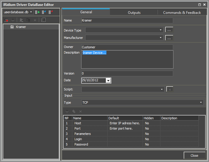
Tools for creating new devices in iRidium data base are available in the right-click menu. The type of the created device - TCP (TCP Device) – defines its characteristics. For TCP devices you can indicate information about the manufacturer, type of the controlled equipment, comments and commands.
Setting Up TCP Devices
Creation of description for new devices is not compulsory but it can help with their further identification
- Device Type – a type of the controlled device (TV, DVD, Blu Ray, ...)
- Manufacturer – the name of the device manufacturer
- Description – description of the device, it can include hyper links
- Date – the date of creating the driver
TCP devices have the following properties for connection:
- Host – an IP-address of the controlled Kramer device in your network.
- Port – a port the device works through.
Optional properties:
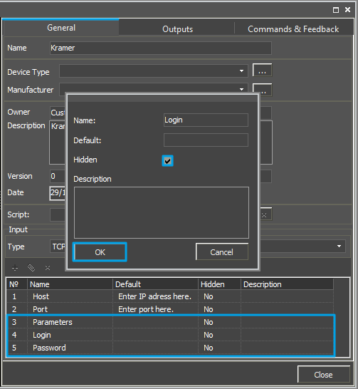
- Parameters – additional properties for connection
- Login – a login for connection
- Password - a password for connection
These optional properties are used seldom and if you are not going to use them it is recommended to hide them: click two times on each property to open the window for settings and select Hidden.
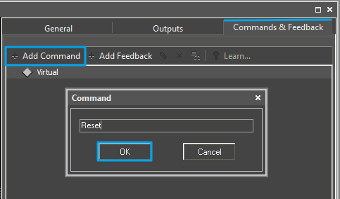
To add the command in the list of the created device go to the Commands & Feedback tab and use tools of the Editor base:
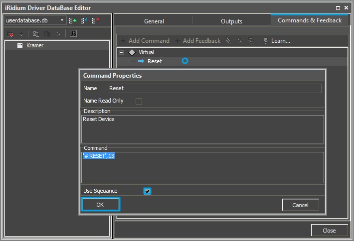
The command is created empty by default. The instruction the command should send is indicated in the Command Properties windows. Click two times on the created command to open the Command Properties window.
- Write the instruction for the command in the Command field of the opened window. In our case for the Reset command (device resetting) there is the '# RESET',13 instruction, where ,13 is a symbol of the string end and # RESET is the instruction content (the command is sent in the ASCII format).
- Mark the Name Read Only field if you do not want to change the command name in the future (it is used when the driver works with scripts which refer to the command identifying it by its name).
- In the Descriptions field indicate the command description.
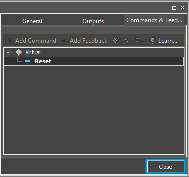
- Now you can close the DB Editor window.
Syntax of TCP Commands
Commands for sending via the TCP protocol cannot be added to DB Editor without checking them for compliance with the syntax accepted in iRidium. It allows you to identify the command data format and form the command correctly so it could be read by the controlled equipment.
The syntax of data sending via TCP (Ethernet or Wi-Fi) defines the rules for sending data in one of the formats selected by the user - ASCII, HEX, DEC.
Sending Commands in the ASCII (Strings) Format
To indicate a string in the ASCII format in the "Data" window write the string in ‘single quotes’. In the end of the string it is required to use the symbol of «string end»:
| Syntax | ‘ + string + ‘ + end |
| End | ,13 (,$0D or ,0x0D) |
| Data | ‘string’,13 (‘string’,$0D or ‘string’,0x0D) |
- all suggested variants of writing are equivalent
In some cases besides the symbol of «string end» it is required to indicate the symbol of «carriage shift» as follows: ,10 or ,$0A or ,0x0A. In this case the command string (the content of the Data window) will look as follows:
‘string’,13,10
‘string’,$0D,$0A
‘string’,0x0D,0x0A
Sending Commands in the HEX (Hexadecimal) Format
To send a string in the HEX format write $ or 0x before each HEX symbol in the "Data" window. In the end of the string it is required to use the symbol of «string end»:
| Syntax | $HEX + ,end |
| End | ,$0D или ,0x0D |
| Data | 0x01,0x02,0x03,0x0D ($01,$02,$03,$0D) |
- all suggested variants of writing are equivalent
Besides the symbol of «string end» you can indicate the symbol of «carriage shift»: ,10 or ,$0A or ,0x0A. In this case the command string (the content of the Data window) will look as follows:
$01,$02,$03,$0D,$0A
0x01,0x02,0x03,$0D,$0A
0x01,0x02,0x03,0x0D,0x0A
Sending Commands in the DEC (Decimal) Format
To indicate a string in the DEC format in the "Data" window write data in the decimal format separated by commas. In the end of the string it is required to use the symbol of «string end»:
| Syntax | DEC,DEC,DEC + end |
| End | ,13 (,$0D или ,0x0D) |
| Data | 1,2,3,13 |
- all suggested variants of writing are equivalent
Besides the symbol of «string end» you can indicate the symbol of «carriage shift»: ,10 or ,$0A or ,0x0A. In this case the command string (the content of the Data window) will look as follows:
1,2,3,13,10
Examples of using the syntax (ASCII, HEX, DEC):
Adding TCP Devices to iRidium Projects
- Create a new project. New projects can be created with the help of the button on Tool Box or through the menu File > New Project.
You can find more information about project creating in the section Creating the Graphic Part of iRidium Projects
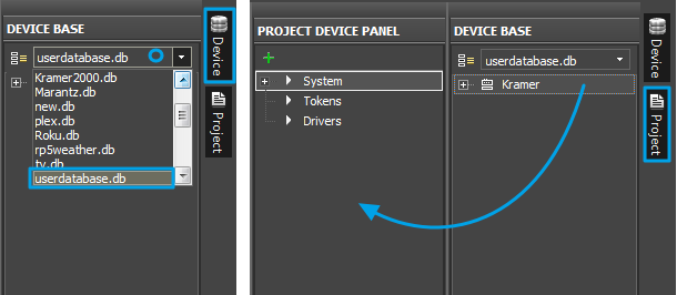
Select the kramer.db data base in the Device Base panel and add the Kramer device you have in Project Device Panel of your project using the Drag&Drop method.
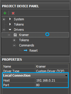
To connect iRidium to Kramer, indicate the local IP-address in general settings of the device in the PROPERTIES window of the Project Device Panel:
- Host – an IP-address of the controlled Kramer device.
- Port – a port the device works through.
To work with the Kramer device via the Internet indicate the public IP-address of the router the converter is connected to. Set up the Port Forwarding Service for the router which enables possibility of referring to the local address of the controlled converter from the Internet (remote control).
You can learn the external (public) IP-address of your router with the help of external resources, for example [1]
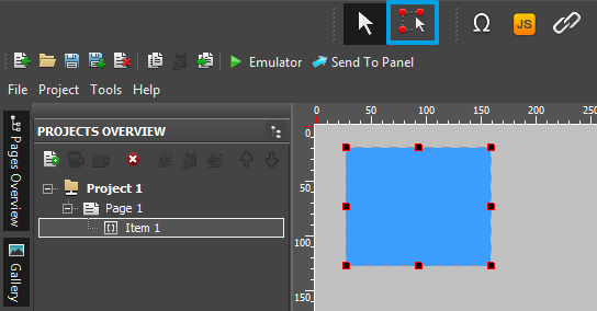
Select the Draw Item tool and create a new item.
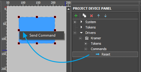
Open commands of the Kramer device and drag the Reset command on the item. Select send command in the appeared window.
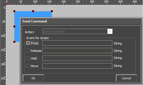
In the Send Command dialog window select the type of the event which will activate command sending to the device.
- Press – pressing on the item
- Release – releasing the item
- Hold – holding the item
- Move – moving on the item (it it mainly used for the Level item type)
The Press event is indicated by default as the most commonly used.
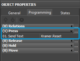
The commands added on the item can be seen in the Programming tab of the Object Properties panel.
Launch Emulator to check how the command works.
Switching Local and Public IP-addresses of Global Cache
To change properties of connection to Global Cache in the process of project work on the control panel use the method based on using a simple script function (SetParameters).
It is used when it is required to control the automation object via the Internet: switching the local and external IP-interface of the automation system.
How to set it up in your project:
To add the function of changing the connection settings in your iRidium project open the script editor in iRidium GUI Editor.
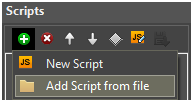
Add the ready module template with the SetParameters function in your project (Add Script from file) after downloading it from HEREor create a new empty module (New Script):
Set up the function and duplicate it as many times as you need:
function Internal()
{
 IR.GetDevice("AV & Custom Systems (TCP)").SetParameters({Host: "192.168.0.100", Port: "8080"});
}

function External()
{
 IR.GetDevice("AV & Custom Systems (TCP)").SetParameters({Host: "210.110.10.10", Port: "8080",});
}
In the function settings indicate:
- Internal (or External, or another) – the name of the function. Indicate this name in the settings of the button pressing on which will activate the corresponding function. Two functions of one project should NOT have the same name!
- "AV & Custom Systems (TCP)" – the name of the driver in the project tree the function will be activated for.
- Host: "192.168.0.100", Port: "8080" – the set of properties of connection to the AV device which will be used after activating the function.
Activation of the function created with the help of iRidium Script is performed with the Script Call command. The command should be added for the Press or Release button which changes the properties of connection to the AV device.
Go to the macros editor of the button, select the Script Call command and assign it to the button the by double-clicking on it. In the drop-down list you will see the list of the SetParameters functions created by you. Select the function (the set of properties) which corresponds to the button:
![]() To work with AV & Custom Systems (TCP) via the Internet indicate the public IP-address of the router the device is connected to. Set up Port Forwarding for the router to enable remote control – referring to the local (private) address of the controlled AV device via the Internet.
To work with AV & Custom Systems (TCP) via the Internet indicate the public IP-address of the router the device is connected to. Set up Port Forwarding for the router to enable remote control – referring to the local (private) address of the controlled AV device via the Internet.
You can learn the external (public) IP-address of your router with the help of external resources, for example [2]
Downloads
Download: Example of a project for controlling the Kramer commutator via ТСР (1 Mb)
<< back (AV & Custom Systems: Working with Equipment via TCP)
