AV & Custom Systems (UDP)
Contents
- 1 Principles of Controlling Equipment via UDP
- 2 Creation and Setting up of the AV & Custom Systems (UDP) Driver
- 3 Structure of the AV & Custom Systems Driver
- 4 Sending Commands to AV Equipment
- 5 Working with AV & Custom Systems (UDP) Commands
- 6 Creation of Your Own Base of AV & Custom Systems (UDP) Commands
- 7 Switching Between the Local and Internet Connection
- 8 Downloads
iRidium for AV & Custom Systems (UDP) allows you to control any equipment with Ethernet-interfaces or Wi-Fi modules. The control is performed via UDP/IP, locally or via the Internet.
Conditions for working with the driver:
- possibility to control the selected equipment via UDP/IP
- commands for controlling equipment via UDP/IP and the protocol
- possibility to create scripts if the protocol suggests authorization and requires data exchange with control panels
Description of driver work:
The "AV & Custom Systems (UDP)" driver opens and supports connection session with equipment via UDP/IP. Then the connection is established, you can send commands to the connected equipment – the list of commands is formed by the user in the process of creating a project. Feedback from the equipment is received by processing data by the script crated in the iRidium project iRidium (see iRidium DDK and iRidium Script API).
![]() These instructions describe creation of scripts for processing data received from equipment. Receipt of feedback from equipment is described in the iRidium DDK section.
These instructions describe creation of scripts for processing data received from equipment. Receipt of feedback from equipment is described in the iRidium DDK section.
Principles of Controlling Equipment via UDP
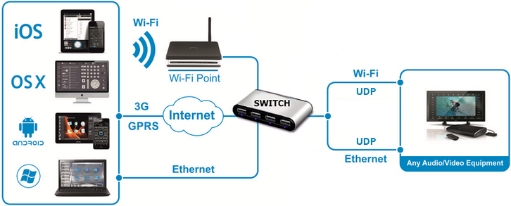
In iRidium you can use the universal "AV & Custom Systems" (UDP) driver to connect to your Audio-Video and other equipment. The scheme of communication between iRidium and controlled equipment:
Protocol for data sending: UDP/IP.
Supported formats of data exchange: ASCII, HEX, DEC.
Use iRidium syntax for writing commands in different formats.
Feedback from equipment: there is none in the standard variant. It is implemented with the help of iRidium Script, see iRidium DDK.
Required licenses: Device License Pro for AV & Custom Systems (see. Licensing). It works with any equipment controlled with the help of "AV & Custom Systems". It enables use of any scripts in your projects.
Creation and Setting up of the AV & Custom Systems (UDP) Driver
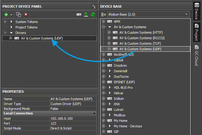
Select the AV & Custom Systems tab in the DEVICE BASE window of iRidium GUI Editor. Open it and find "AV & Custom Systems (UDP)". Drag the driver into the PROJECT DEVICE PANEL window:
Properties of connection to equipment using AV & Custom Systems (UDP):
- Host – the IP-address of the controlled equipment (local, external or the domain name)
- Port – the UDP port for connection to equipment
- Script Mode – the mode of command sending and communication with scripts in iRidium projects
- Direct & Script – data from the command will be sent directly to the equipment and processes by the script system
- Script Only – commands created inside the driver are not sent directly to the equipment but are processed by the script system first.
To connect to equipment via the Internet:
- 1. Indicate the public address of your Internet router in the Host field
- 3. Set up Port Forwarding on your router to enable remote control of your equipment .
- You can learn the public IP-address of your router with the help of external resources, for example [1]
To switch between local and Internet connection:
Use the example presented below.
Structure of the AV & Custom Systems Driver
The AV & Custom Systems in iRidium projects consists of 3 parts:
- Driver Tokens – the list of variables which store information about connection to equipment
- Commands – the list of commands which can be sent to equipment (or script) by pressing interface buttons
- Feedbacks – the list of feedback channels where data from the controlled equipment (processed by the iRidium script system) can be written.
Properties and applications of the driver parts:
Driver Tokens
Driver Tokens - variables storing the status of connection to the controlled equipment. These properties can be read only.
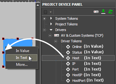
To use a token, drag it on the graphic item (the token value can be output in the item text field or it can be used to change the item state).
| Online | a state of connection to the controlled system (Online/Offline = 1/0) |
| Status | the status of connection to the system (Offline/Connecting/Online/Waiting = 0...3) |
| Host | the domain name of the remote system |
| HostPort | the port of the remote system to which iRidium App is connected |
| IP | the IP-address of the control panel |
| HostIP | an IP-address of the remote system to which iRidium is connected |
| Port | the local port of the client through which the connection to the remote device is established |
Commands and Feedbacks
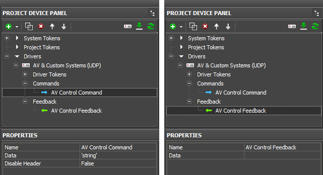
Commands – the list of commands which can be sent to the equipment (or scripts) by pressing interface buttons. It is filled at random. The number of commands is not limited.
Feedbacks – the list of feedback channels where data from the controlled equipment (processed by the iRidium script system) can be written. The data written in the Data filed of the Feedback channel can be read using the script.
Commands
- Name - the command name, at random
- Data - the data the command has to send at the activation. They can be written in HEX, DEC, ASCII
- Desable Header – it is used only for Global Cache modules and ready script drivers. Leave “False” by default.
Feedback
- Name – the feedback channel name. You can refer to the channel from scripts for writing data.
- Data – the data which the feedback channel stores at the project launch. They can be rewritten with the help of graphic item commands or scripts.
To assign a command to a graphic item:
drag it on the graphic item and select the event on which it should be sent:
- Press – pressing on the item
- Release – releasing the item
- Hold – holding the item
- Move – moving on the item (it is mostly used for Level)
To assign a feedback channel to a graphic item:
drag it on the graphic item and select what it should affect:
- In Value – when receiving any non-zero value the item will change its state (State 1/State 2). It is used for visualizing changes by changing the item appearance.
- In Text – when receiving any data they will be written in the item text field
- More... – the received data can affect any other item properties (see the available properties in the dialog window)
Sending Commands to AV Equipment
Select the commands you need to add in the list of the AV & Custom Systems (UDP) driver. They can be stored in one of the following formats:
- ASCII - string
- HEX – hexadecimal
- DEC - decimal
You need to prepare the information which is stored in one of these formats correctly so iRidium could process it and send to the equipment. Use iRidium "syntax" for forming commands of the AV & Custom Systems driver. The syntax is similar for TCP, UDP, RS232.
Characteristic features of sending commands via UDP:
The protocols of data exchange with equipment include instructions for the equipment and rules for forming commands. Commands for TCP and RS232 usually end with обычно завершаются символами "carriage return" <CR> and "line end" <LF> symbols. Commands for UDP (with a few exceptions) usually work without them.
If your documentation requires using использовать "carriage return" <CR> and "line end" <LF> symbols, form them as follows:
| In documentation: | <CR> | <CR> | <CR> | <LF> | <LF> | <LF> |
| In iRidium (the Data field): | 0x0D | $0D | 13 | 0x0A | $0A | 10 |
If these symbols are not indicated in your documentation, do not add them.
Commands in the ASCII Format (Strings)
Add a ASCII string in the "Data" window:
- include it in ‘single quotes’.
- if the string is followed by data in a different format, separate them with commas
| Initial command (in documentation): |
PWR01 | VOLUME 50 | AUD 1>3 | 6CH/8CH <CR> <LF> |
| In iRidium (the Data field): |
'PWR01' | 'VOLUME 50' | 'AUD 1>3' | '6CH/8CH',0x0D,0x0A |
The "carriage return" <CR> and "line end" <LF> symbols should be used only if they are indicated in the documentation.
Commands in the HEX (Hexadecimal) Format
Add HEX data in the "Data" window:
- write $ or 0x before each HEX symbol
- do not use blank spaces, divide HEX symbols with commas
- if there are additional symbols near HEX symbols in your documentation, remove them (FFh > FF)
| Initial command (in documentation): |
01 81 81 81 | 19h EEh A1h C1h | 16 8A FF FF <CR> <LF> |
| In iRidium (the Data field): |
0x01,0x81,0x81,0x81 | 0x19,0xEE,0xA1,0xC1 | 0x16,0x8A,0xFF,0xFF,0x0D,0x0A |
The "carriage return" <CR> and "line end" <LF> symbols should be used only if they are indicated in the documentation.
Commands in the DEC (Decimal) Format
Add DEC data in the "Data" window:
- do not use additional symbols
- do not use blank spaces, divide symbols with commas
| Initial command (in documentation): |
01 255 255 05 25 | 20 30 40 50 <CR> <LF> |
| In iRidium (the Data field): |
01,255,255,05,25 | 20,30,40,50,13,10 |
The "carriage return" <CR> and "line end" <LF> symbols should be used only if they are indicated in the documentation.
Working with AV & Custom Systems (UDP) Commands
Example of using commands for AV & Custom Systems (UDP):
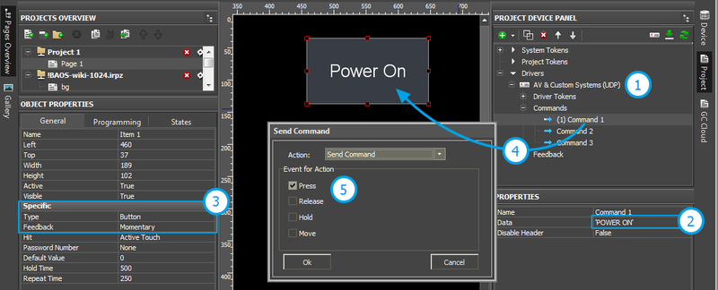
- 1. Add the AV & Custom Systems (UDP) driver in your iRidium project. Set up properties of connection to the equipment.
- 2. Create a command. Indicate data for sending to equipment in the Data field.
- 3. Set up the button which will be responsible for sending the command.
- Type: Button
- Feedback: Momentary
- 4. Drag the command on the button.
- 5. Select the event the on which the command will be sent:
- Press – pressing on the item
- Release – releasing the item
- Hold – holding the item
- Move – moving on the item (it is mainly used for Level)
![]() You cannot change the command in the Data field when the project is already uploaded on your control panel. It means that if your command, for example, is responsible for setting the volume to 50%, it cannot be assigned to Level for gradual volume regulation. It will work only with Button and set the volume to 50% at each pressing.
You cannot change the command in the Data field when the project is already uploaded on your control panel. It means that if your command, for example, is responsible for setting the volume to 50%, it cannot be assigned to Level for gradual volume regulation. It will work only with Button and set the volume to 50% at each pressing.
![]() To send values (e.g. volume) сfrom Level, you need to from the command with the help of scripts (see iRidium Script API and iRidium DDK), not in the project tree.
To send values (e.g. volume) сfrom Level, you need to from the command with the help of scripts (see iRidium Script API and iRidium DDK), not in the project tree.
Creation of Your Own Base of AV & Custom Systems (UDP) Commands
To use AV & Custom Systems (UDP) in any iRidium project you need to save it in the iRidium data base.
Use DB Editor for adding devices. New devices can be added only to custom data bases as standard data bases cannot be edited.
![]() Creation of data bases is not the only way of transferring commands from one iRidium project to another. If you created a device with commands in your iRidium project, you can import it to another project using File > Import > *.irpz
Creation of data bases is not the only way of transferring commands from one iRidium project to another. If you created a device with commands in your iRidium project, you can import it to another project using File > Import > *.irpz
Creating Data Bases
Use custom data bases for storing your devices. They are created in DB Editor. When creating a data base, indicate its name and directory for saving.
Use your own data bases (created manually) for storing your devices not standard data bases which can be updated with releases of new versions of iRidium GUI Editor. The names of the base file and folder for storing are indicated when creating the file.
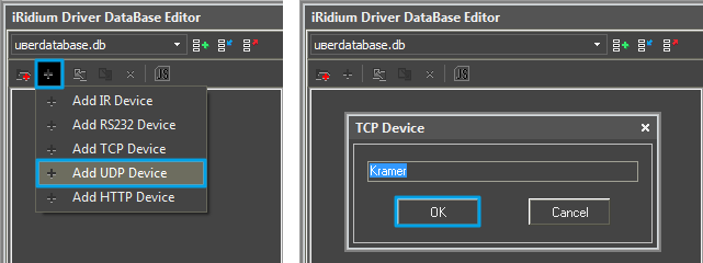
Creating new UDP devices:
The type of the created device - UDP (UDP Device) – defines its transport part and characteristics.
Tools for creating new devices in iRidium data base are available in the right-click menu. The type of the created device - UDP (UDP Device) – defines its characteristics. For UDP devices you can indicate information about the manufacturer, type of the controlled equipment, comments and commands.
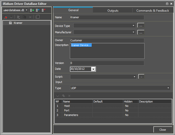
Setting up UDP devices
Describe new devices to help with their further identification:
- Device Type – the type of the controlled device (TV, DVD, Blu Ray, ...)
- Manufacturer – the name of the device manufacturer
- Description – description of the device, it can include hyper links
- Date – the date of creating the driver
Properties for connection:
- Host – the IP-address of the device in your network
- Port – the port the device uses
Optional properties:
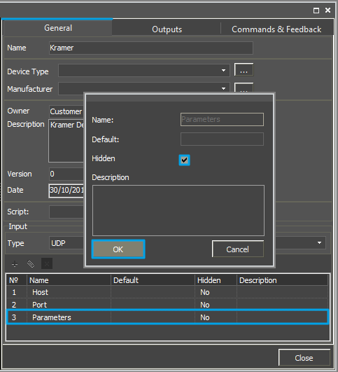
- Parameters – additional properties for connection
The optional properties can be hidden: click two times on the property to open the window for settings and select Hidden.
Adding commands in the list of devices
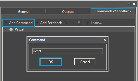
Go to the Commands & Feedback tab and use tools of iRidium GUI Editor:
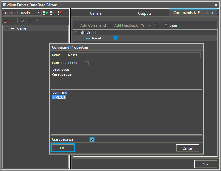
The command is empty by default. The instruction the command should send is indicated in the Command Properties window. Click two times on the created command to open the Command Properties window.
- Write the instruction for the command in the Command field of the opened window. In our case for the Reset command (device resetting) there is the # RESET instruction (the command is sent in the ASCII format).
- Mark the Name Read Only field if you do not want to change the command name in the future (it is used when the driver works with scripts which refer to the command identifying it by its name).
- In the Descriptions field indicate the command description.
When all commands are added, you can close the DB Editor window.
Switching Between the Local and Internet Connection
If the control panel should hold the connection with the system when the panel is out of the limits of the Wi-Fi network of the system, you need to set up the switch between the Internet and the local network.
The remote mode suggests connection to the system via the Internet. At that the external IP-address or the domain name of the system to which you need to connect have to be used.
 In iRidium Wi-Fi/3G CANNOT be switched automatically. For switching between the Internet and the local network you need buttons with special settings. See the settings below.
 To control the system remotely you have to open the system for external access -
to set up the Port Forwarding Service.
 To secure equipment from unauthorized access we recommend using secure connection with the remote system (VPN).
Setting up of the switch Wi-Fi/3G in iRidium projects:
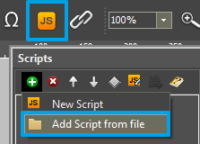
1. Open the script editor in iRidium GUI Editor.
2. Download and add into your project the template of the Wi-Fi/3G switch (Add Script from file):
download the template of the Wi-Fi/3G switch
The Wi-Fi/3G switch is performed with the help of the script function SetParameters
Setting up of parameters of the Wi-Fi/3G switch:
- function Internal_1() // Function name
- {
- IR.GetDevice('AV & Custom Systems (UDP)').SetParameters({Host: '192.168.0.100', Port: '1000'}); // Driver Name + Parameters
- }
- function External_1()
- {
- IR.GetDevice('AV & Custom Systems (UDP)').SetParameters({Host: '220.115.10.10', Port: '1000'});
- }
Indicate in the command settings:
- Function name – the name of the switch function (command). Two functions cannot have the same name in a project.
- Driver Name – the name of the driver which parameters are changed
- Parameters – the set of the switch parameters which you need to apply to the driver
Assign commands to buttons:
- Select the button which will be responsible for the Wi-Fi/3G switch.
Open the properties of the button: Object Properties > Programming - Open Macros Editor of the button for the Press or Release events
- Select the Script Call command and add it by double-clicking on it
- Select the name of the function you want to activate in the drop-down list. Create the command.
Set up access to the equipment from the Internet:
In order to do that open the equipment ports for remote access.
Download the example of the Wi-Fi/3G switch (project) >>
Downloads
Download: Example of a project for controlling the Kramer commutator via UDР (1 Mb) Example of switching Wi-Fi/Internet for AV & Custom Systems
