General Settings of iRidium GUI Editor
Contents
Tool Box and the GUI Editor Interface
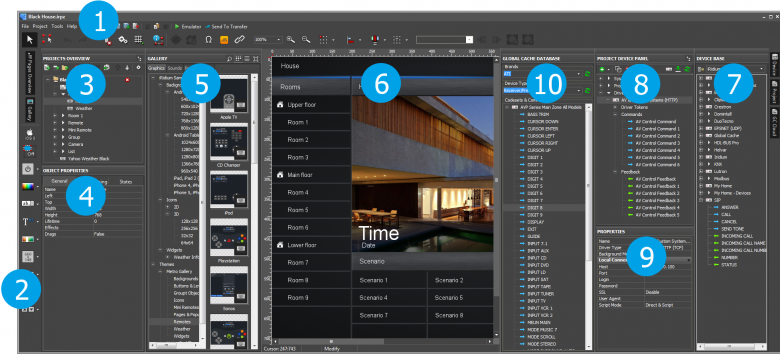
After starting iRidium GUI Editor you can see the workspace which consists of several zones:
- Tool Box: contains main Editor tools and shifts to settings.
- Box of drawing tools: contains tools for fast drawing of graphic items. After selecting a style and indicting the scaling possibility, you can add buttons, levels and other objects in projects fast and easy.
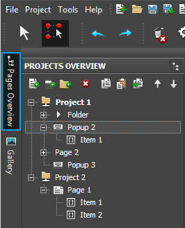
- Project Overview: displays the structure of the project graphic part, enabling you to add new items to it (pages, popups, folders).
- Object Properties: the part of the Project Overview panel. It contains information about the selected GUI object – a page, popup or graphic item.
- Gallery: the gallery of images and sounds which can be used when creating an interface.
- Workspace: displays appearance of pages and popups selected in Project Overview. Here graphic items for project pages and popups are placed. The commands to items are also assigned here.
- Device Base: the database of built-in iRidium drivers (products). It includes tools for creating drivers for users and additional databases of script drivers.
- Project Device Panel: displays the drivers used in the project and all their commands and channels. The commands can be dragged into the editor workspace (on items).
- Properties: the part of the Project Device Panel. The properties of the selected driver, command or channel are set up here.
- Global Caché Cloud: the database of IR commands for using with Global Caché converters.
Tool Box
Tool Box contains buttons for activating Editor tools and settings. It includes side buttons for opening GUI Editor panels.
| Emulator
Start the GUI emulation mode |
Send To Panel
Send the GUI to the control panel | ||
| Zoom
Selected scale of the GUI Editor workspace |
Current State
Current state of the graphic item in the workspace |
Project Overview
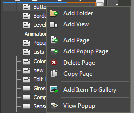
Project Overview is opened by clicking the button on the left side panel of GUI Editor. It allows you to create new project pages (Pages) and popups (Popup Pages). The page or popup selected in Project Overview are displayed in the Editor Workspace.
Workspace
Workspace is used for creating and positioning graphic items on project pages and popups.
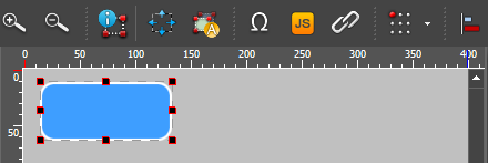
You can create items, set up their size and position in Workspace. Here you can also set up Workspace scale, grid displaying, add or remove item states, switch between the item states and set up particular properties of items and item groups with the help of the Tool Box objects:
The rest properties of Editor Workspace objects are set in the Project Overview tab in the Object Properties window.
| Select – move among the workspace objects | |
| Draw Item - create a new object in the workspace |
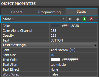
To create or delete a graphic item state (State) and go from one state to the other faster use the tools (Object Properties > States):
| Current State - the current selected state of the graphic item |
| Prev State - open the previous state | |
| Next State - open the next state | |
| Add State - add one more state to the selected | |
| Delete State - delete the selected state |
Object Properties
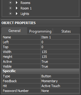
Object Properties is a part of the Project Overview panel. It contains information about the selected GUI object – a page, popup or graphic item.
|
The «Object Properties» window contains 3 tabs:
|
Box of Drawing Tools
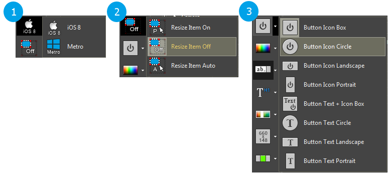
The box of drawing tools is a convenient instrument both for beginners and experienced users. It helps to create items and blocks of interface items fast selecting them from the ready list of templates. Templates can be created in different styles and items added from them can be scaled.
The box is on the left side of iRidium GUI Editor. Working with the box includes three stages:
- style selection – to define how the item templates will be drawn
- scaling method selection – to add items in their initial size or scale them
- item template selection – depending on what item has to be created
When the instrument is set up and selected, you can go to the editor workspace, on a project page or popup and start creating items the same way it’s done by the standard tool for drawing buttons.
Gallery
Gallery contains images, sounds and settings for receiving data from IP cameras. You can use all of them when creating your GUI. Gallery consists of global Gallery and Project Gallery. Project Gallery contains the objects used in the project.
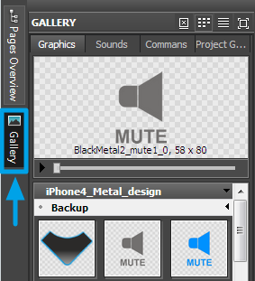
|
Properties of displaying Gallery objects
(the right top corner of the Gallery window): |
|
Setting up of dynamic images (links to IP cameras) is performed in the Project Gallery tab in the ) Dynamic Images section. |
Device Base
Device Base – the list of native drivers, commands and script modules for controlling various equipment. All iRidium supported devices which you can use in your projects are stored here.
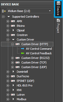
|
Tools of Device Base: |
| Actions with databases are available in the Database Edit window: | |
In Device Base Editor you can create custom drivers for controlling equipment, select the device type, create commands, feedback channels and script modules for data processing.
DB Editor is used for professional setting up of equipment and creating custom devices on the base of the Custom driver (TCP, UDP, HTTP, RS232) with the help of iRidiumScript:
Project Device Panel
Project Device Panel – the list of devices you want to control in your iRidium project. Properties, commands and channels of connection to equipment are set up here.
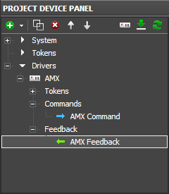
|
In the System tab of the tree there is a list of system variables (for example, current date and time) which can be used in projects дерева. You can also create tokens here – global variables (memory cells that are not directly connected with equipment). | |||||||||||||
|
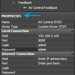
A created device (command, channel, token) is set up in the Properties window:
Properties
Properties the window which contains information about settings of connection to equipment, settings for commands (Commands), feedback channels (Feedbacks) and tokens (Tokens).
Object properties selected in the Project Device Panel tree (settings for connection with equipment – an IP-address, port, specific equipment properties; properties of commands and status channels) are displayed in this window.
Iridium Driver DataBase Editor
Iridium Driver DataBase Editor – the tool for creating devices and commands on the basis of the Custom/AV driver. It is a professional tool which enables you to set up control of any AV equipment, media server or other devices with the help of IRidium DDK
To open Iridium Driver DataBase Editor press the Edit ![]() button on the Device Base panel.
button on the Device Base panel.
JS Editor
JS Editor the tool это for creating script modules to control GUI items and script drivers in iRidium projects.
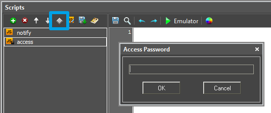
Scripts – opens JS Editor.
Settings of GUI Editor Workspace
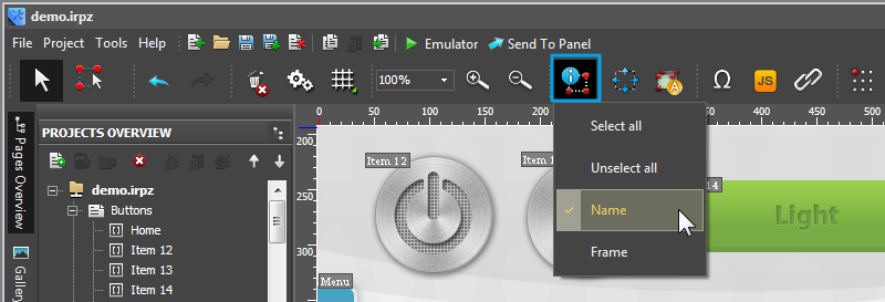
When working with GUI Editor you can select which graphic item properties you want to display in Workspace. The selection is made in the dropdown list of the View Info button in GUI Editor Tool Box:
There are the following actions in the dropdown list:
- Select all – select all items on the page
- Unselect all – unselect all items
- Name – display the name of the graphic item in Workspace
- Frame – display the border of the graphic item in Workspace
- Cannal count - to display a number of bound commands (under developement)
- System Info - under developement
Settings of GUI Editor
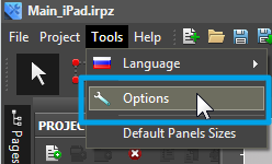
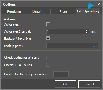
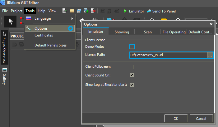
Properties for importing Gallery objects, project Emulation, displaying items, checking updates, network scanning, auto-saving and saving project backup copies are set in the window of main settings in iRidium GUI Editor. You can set up these properties through the Tools > Options menu:
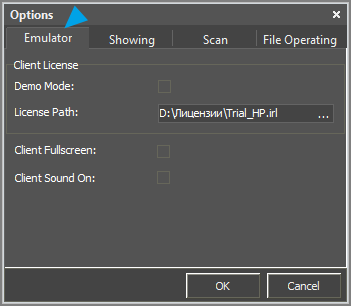
1. The "Emulator" tab – Emulator settings in Editor.
Work of Emulator (either with connection to equipment or without it) is set up in the Client License section.
- Demo Mode – activation of work without licenses (without connection to equipment)
- License Path – a path to the license file for Windows when the Demo Mode is deactivated
- Client Fullscreen – launching Emulator on the full screen
- Client Sound On – playing sounds in Emulator
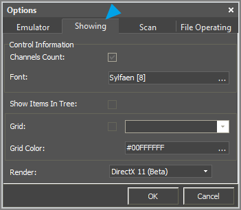
2. The "Showing" tab – settings for displaying objects in Editor Workspace
- Channels Count – displaying the number of commands assigned to the item
- Font –size and type of the font which will be used for displaying information about the item in Editor Workspace (item name, number of commands, etc.)
- Show Items In Tree – showing the list of graphic items on the page in the tree of project pages
- Grid – activation and setting up the grid in Editor Workspace
- Grid Color – selecting the color of the grid
- Render – a type of Editor Workspace rendering
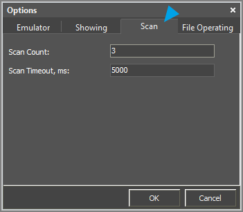
3. The "Scan" tab – settings for scanning of the HDL-BUS Pro network
- Scan Count – the number of network scanning cycles
- Scan Timeout, ms – length of one scanning cycle in ms
4. The "File Operating" tab – settings for project auto-saving and backup, Editor updating and importing files in Editor Gallery
- Autosave, Autosave Interval – activation of auto-saving and indicating the auto-saving interval in minutes
- Backup, Backup Path – activation of creating the project backup at each project saving. Only the configuration file (without library of images) is saved. To use the file you have to unpack the damaged irpz project as a zip archive and substitute the project irp file by the one saved in backup.
- Check updates at start – checking for updates at each launch of Editor
- Check BETA-builds - checking for Editor beta version at each launch
- Divider for file group operations – the symbol dividing the state number from the image name when importing dynamic objects in Editor Gallery.
Setting Up Projects in GUI Editor
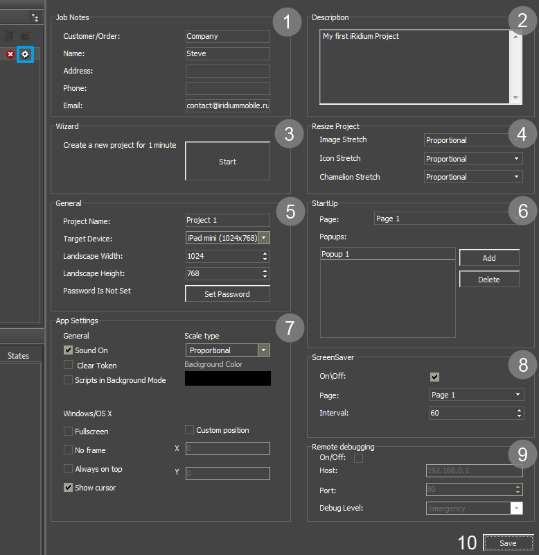
The project properties can be set in the Project Properties tab you can access one of the following ways:
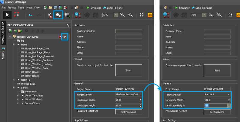
You can also access to Project Properties from Tool Box of iRidium GUI Editor or with the help of the button near the project name:
- 1. Job Notes (information about the project)
- Customer/Order
- Project Name
- Address – the address of the automation object
- Phone – the customer phone number
- Landscape Width/Height – the project resolution when displaying it in the Landscape (horizontal) mode (in pixels). The projects which have the Portrait orientation the size should be written as width/height for horizontal pages.
- 2. Description (notes about the project, version history)
- 3. Wizard (fast creation of interfaces from the ready pages)
- it is used for creating a project from the standard ready pages. After adding the pages to the project it is necessary to link them by navigation commands to be able to go from one page to another. - 4. Resize Project (settings of project scaling)
- it is used when you change the resolution in the General tab of the project settings. They affect on the appearance of images and icons (if they are stretched or not, etc.). - 5. General (main project properties)
- Project Name – used when saving the project
- Target Device – the device you plan to launch your project on. It defies the GUI resolution.
- Landscape Width – the width of the horizontal project page. You should indicate the value for the horizontal page even if your project is vertical.
- Landscape Height – the height of the horizontal project page. You should indicate the value for the horizontal page even if your project is vertical.
- Password – the password for project opening and editing
- 6. StartUp (start settings)
- Page – indicate the page which will open after you start the project
- Popups – indicate the list of popups which should open over the start page. They will open one over another in the order you indicate.
- 7. App Settings (properties of the iRidium App application when working with the project)
- General – the settings used for all OS
- Sound On – to turn all sounds in the application on/off
- Clear Token – to clear/store data from Project Tokens when relaunching the application
- Scripts in Background Mode – not to stop work of scripts when the application works in the Background mode
- Scale Type [Proportional/FullSize/None] – the way of scaling the interface to the size of the control panel
- None – not to scale
- Proportional – to scale to the size of the panel saving proportions
- Full Size – to scale to the size of the panel without saving proportions
- Background Color – filling of the empty areas on the screen when the project proportions or resolution does not correspond to the size of the panel screen
- Windows/OS X – settings are used only on настройки Windows/OS X
- Fullscreen – to launch the project in the full screen mode
- No Frame – to add/remove the application frame
- Always on top – to show above all popups
- Show cursor – to show/hide the cursor
- Custom position [X/Y] – to open the application window in the selected area of the screen
- 8. Screensaver
- Page – the name of any project which will be used as a screensaver
- Interval – the time (sec)during which the project should not be interacted so the screensaver could open automatically
- 8. Remote Debugging (see here)
Changing of the Project Resolution (Scaling)
Save the project backup copy before scaling.
To change the project resolution, for example make the 1024x768 project from the 2048х1536 project, write the required resolution in the project properties. At that, it is recommended to make projects of lower resolution from high resolution projects to avoid problems with graphics quality.
After saving the project in the new resolution you will see two dialog windows:
1. Confirm scaling
- "Ok" – to confirm changes of the project size
- "Cancel" – the project will save the initial resolution, no actions will be performed
2. Decide if you want to change the size of project popups and graphic items
- "Yes" – the size of project popups and graphic items will be scaled to the new page size
- "No" - the size of project popups and graphic items will stay the same, only the size of project pages will change
Project Encryption
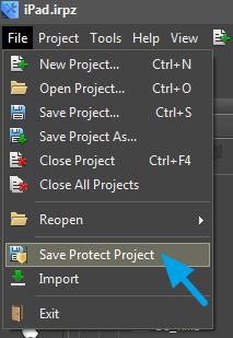
Full project encryption (saving in the protected format)
iRidium projects (*.irpz) can be saved in the protected format. It will forbid third-party users access to project editing, its settings and resources (icons, sounds, images, equipment channels).
Protected projects (*.pirpz) cannot be opened in GUI Editor, but they can be uploaded on control panels where the app will automatically unpack them and start the interfaces.
Project encryption is an irreversible process. A file saved in the *.pirpz format cannot be transformed back into the *.irpz format for editing. The encrypted project is stored next to the initial one. It can be changed only by editing the initial project.
There are also data protection methods inside an *.irpz project which work without encrypting the whole project:
Coding of script files
You can limit access and editing of scripts (iRidium Script) by setting up the access password:
Password for editing
In the settings of iRidium projects (*.irpz) you can set up the password which will be required at each opening of the project. Thus, the project saves the possibility to be edited. Keep in mind that it is possible to import images and script files (do not forget to encrypt them) from *.irpz projects.
Editor Hot Keys
- Ctrl + N - a new project
- Ctrl + O - open the project
- Ctrl + F4 - close the project
- Ctrl + S – save the project
- Ctrl + Z – undo the action
- Ctrl + X – redo the action
- LEFT MOUSE BUTTON – select the item
- RIGHT MOUSE BUTTON – go to the item properties
- Ctrl + C – copy the object (the group of objects)
- Ctrl + X – delete the object (the group of objects)
- Ctrl + V – paste the object (the group of objects)
- Ctrl + A – highlight all objects on the page
- Ctrl + G - group all selected items
- Ctrl + H - ungroup all selected items
- Alt + G - activate/deactivate the current grid
- Ctrl + LEFT MOUSE BUTTON – copy the selected object
- Shift + LEFT MOUSE BUTTON – clone the object on the page
- ← ↑ → ↓ – move the selected object in Workspace (by 1 pixel)
- Ctrl + ← ↑ → ↓ - move the selected object in Workspace (by 10 pixel)
- Shift + ← ↑ → ↓ - resize of the selected object (by 1 pixel)
- Alt + LEFT MOUSE BUTTON – align the text inside the item with the help of the mouse (it is necessary to set up the graphic item properties Text Align = Absolute and fill in the Text field)
- F2 – go to the text editing window - in the current state (State)
- Shift+F2 – go to the text editing window with positioning - in the All States tab (changes the text in all states)
- F4 – open the log window in Emulator
- F5 – run Emulator
- F8 – open the Emulator/iRidium App settings for Windows
Emulation of Project Work
Emulator
- is an iRidium application for Windows which can be launched from GUI Editor for testing your projects. Emulator can work both with a license (with connection to the equipment) and without it (when only the project graphic part is functional).
Operation modes for Emulator (see GUI Editor > Tools > Options > Emulator):
- Without the license (Demo Mode: on) – no connection with the controlled equipment.
- With the license (License Path: [...]) – when the license file is selected, all Emulator functions work and there is connection with the controlled equipment.
Indicate the path to the license file for Emulator (GUI Editor > Tools > Options > Emulator):
* When Demo Mode is activated Gui Editor won’t show the message about starting without the connection to the controlled equipment (without a license). Check if there is a license when setting up your project.
Emulator hot keys
- Click F5 to start Emulator.
- Click F8 to open the Emulator settings (password: 2007)
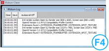
- Click F4 to open the Emulator log.
| For fully functional work of iRidium on your PC it is required to get an iRidium license and activate it for for your PC. Activation of licenses for iPad/iPhone/Mac/Android based or other devices does NOT lead to the automatic licensing of the PC with the installed iRidium Environment. A license for your PC is required for iRidium client on your PC (including Emulator) to work in the fully functional mode. The license should be purchased separately or you can use free For testing purposes you can use free licenses). |
Logging in Windows
iRidium Log is a window where information about iRidium work, error messages and iRidium Script logs (IR.Log) are output in the text format.
To open the iRidium log in Windows, click F4.
