Using Script Drivers
| iRidium JS Drivers |
| [{{{description}}} Description on the web site] |
| [{{{specs}}} Specification] |
| Updated: 27.09.2012 |
| it is a driver created on the basis of the native AV & Custom Systems driver with the help of iRidium DDK. Scripts enable receiving data and communication with ANY equipment. Driver scripts can be created by the user for operation with any control protocol. |
This section present an example of using Script Drivers using the driver for XBMC Media Center 11.0 (Eden).
Contents
- 1 Download the Project Example
- 2 Creating New Projects in iRidium
- 3 Adding the Device Base
- 4 Adding the Device Base to the Project
- 5 Setting up Connection to Equipment
- 6 Using Commands
- 7 Sending Properties to Channels
- 8 Checking the Work of the Command
- 9 Using Channels
- 10 Checking the Work of the Channel
For training you will need an XBMC platform device. If you don’t have one you can download the version XBMC Media Center 11.0 (Eden) from the web site of the manufacturer and use it on your PC. .
Download the Project Example
Demo project for controlling XBMC Eden
Download >>
Creating New Projects in iRidium
- When launching iRidium GUI Editor the first step is creation of a new project or opening of a ready project. New projects can be created with the help of the button on Tool Box or through the menu File > New Project.
You can find detailed description of the project creation in the section Creating the Graphic Part of iRidium Projects
Adding the Device Base
As an example download the base with the script driver for XBMC Media Center 11.0 (Eden)
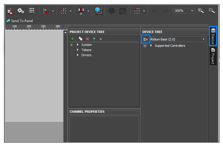
- Work with device bases is performed in iRidium DataBase Editor. To start work with iRidium DataBase Editor go to the Device tab and click on the Edit Base icon.
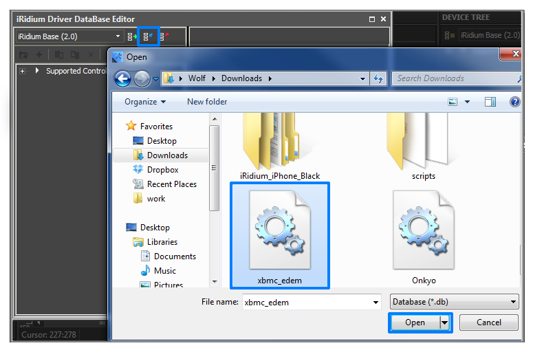
- Press on the Attach Base icon in the open window and select the downloaded base. Then close iRidium DataBase Editor.
Adding the Device Base to the Project
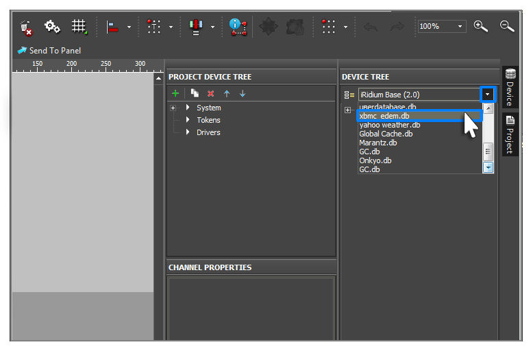
- Go to the Device tab and select the base added by you in the drop-down list.
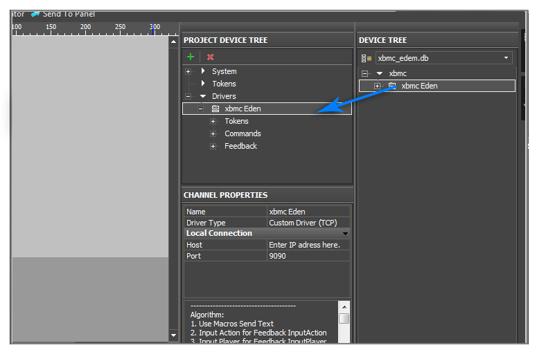
- To use the added base drag it to Project Device Panel.
Setting up Connection to Equipment
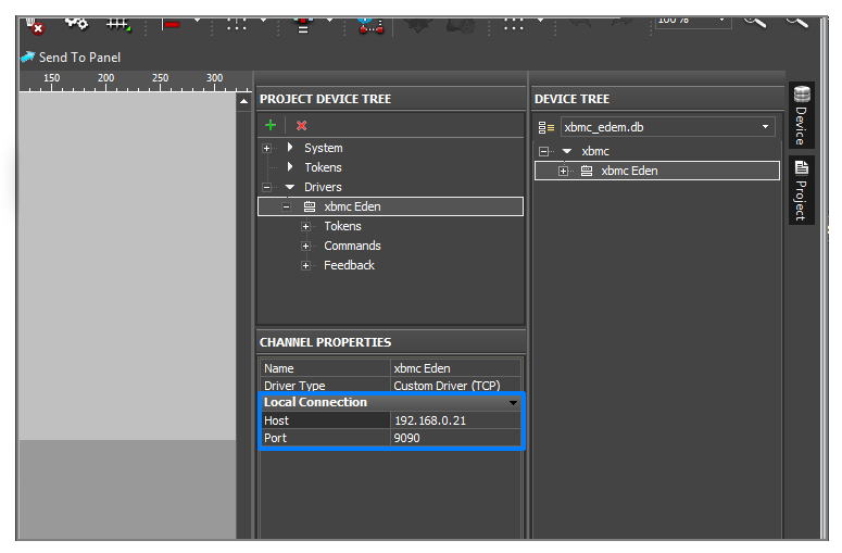
- When the driver is added it is required to select it in the device tree and go to the Properties tab containing settings of the tree components. Settings of connection to the equipment controlled with the help of the driver are indicated here.
- In this case we use the driver working with the | TCP protocol so we should indicate the Host and Port properties.
You can find detailed description of the setting up connection to the equipment in the section Working with Equipment
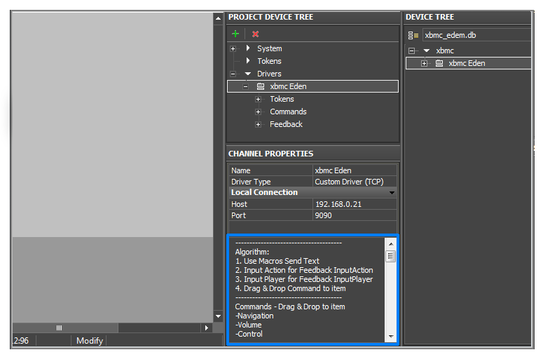
- Each script driver in iRidium has the Description section. It is located under the Properties tab. This section usually contains short information on how to use the driver.
Using Commands
- After setting up the equipment it is required to set up connection between the graphic and driver parts of your iRidium project. The connection of these parts is performed by communication between commands, channels and graphic items of iRidium project.
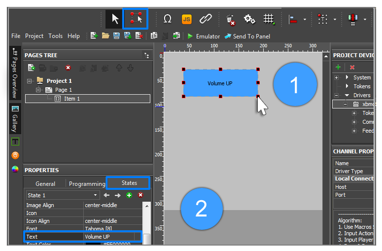
- Use the Draw Item tool on Tool Box to create a template of a graphic item. In our case the graphic item will be used for increasing the volume. To make the purpose of the item clear you can set the Volume UP text for it. In order to do that:
- Go to the tab Object Properties > States
- By default items have two states. Select All States in the drop-down list. You need to do that for the text you want to write on the item to appear on all item states.
- Find the Text field and write Volume UP in it.
You can find detailed information about graphic items in the section Graphic Items
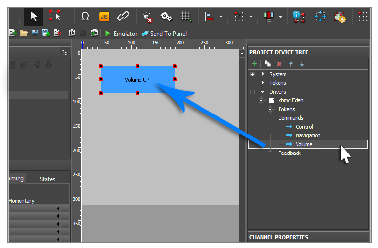
- To assign a command or channel to the graphic item use the Drag&Drop method – drag the tree object to the project graphic item. At that the dialog window will open where you are required to indicate the way of communication between the item and the command. Settings of graphic items directly affect the way of data sending, receiving and displaying.
- For example, when working with the Custom (TCP) driver you can only send data in the information field of the command (Send Command).
- In our case the Volume command is dragged on the item.
You can find detailed information about relation of commands with the graphic part of the project in the section Relations between Commands, Channels and the Project Graphic Part
Sending Properties to Channels
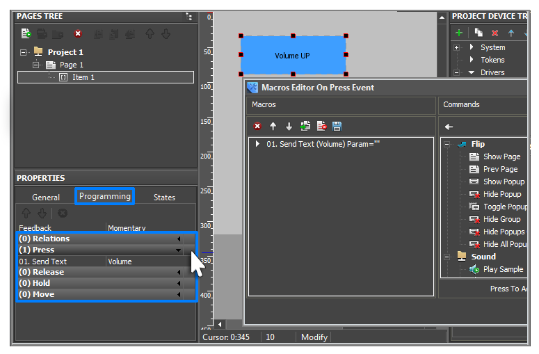
All commands dragged on the item are displayed in the Programming tab.
- Open the Programming tab. The Volume command was added in the Press event. The dragged command is macros. Editing of macros is performed in Macros Editor. Open Macros Editor for the Press event.
- Now when pressing on the item the Volume command is activated. But the command does not know if it should increase or decrease the volume. That is why it is required to assign to the item the macros indicating what to do. There is the Send Text macros for this purposes which gives the property to the driver thus indicating to the command what it should do..
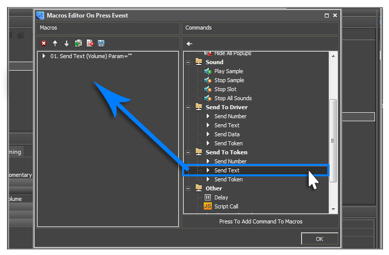
- In the Commands column of the Send To Token section select Send Text and drag it in the Macros column.
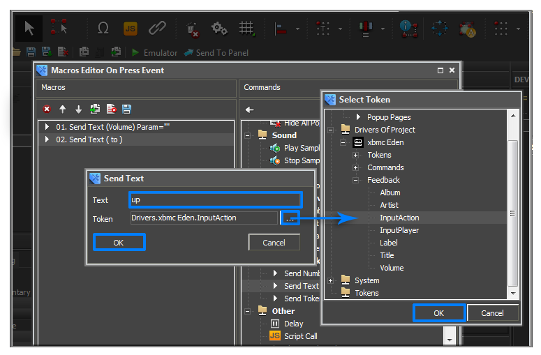
- Indicate the first property for the command, in our case - Up, in the Text field of the appeared window. In the Token field select the channel in the Feedback - InputAction section.
InputAction is used for inputting properties of the command.
In script drivers all channels (Feedback) with the Input prefix are used for inputting properties.
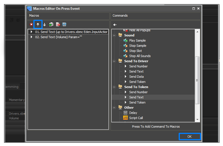
- After adding the Send Text macros it is required to place it above the Volume command for its correct work. It is also necessary so the driver before the activation of the Volume command knew what the command will do. Use the Move Up button to move the Send Text macros up.
For moving macros use Move Up / Move Down buttons.
You can find detailed information about macros and working in Macros Editor in the section Macros (Macros Editor)
Checking the Work of the Command
| Emulator |
|---|
| is a part of iRidium package for Windows aims to check if GUIs work correctly before uploading them onto control devices. Emulator can work both with a license (with connection to the equipment) and without it (when only the project graphic part is functional). |
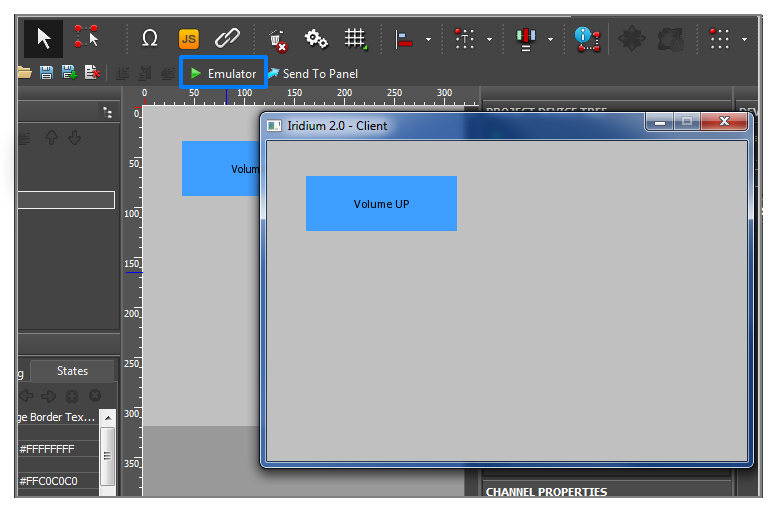
- Launch Emulator; Emulator window will open together with your project.
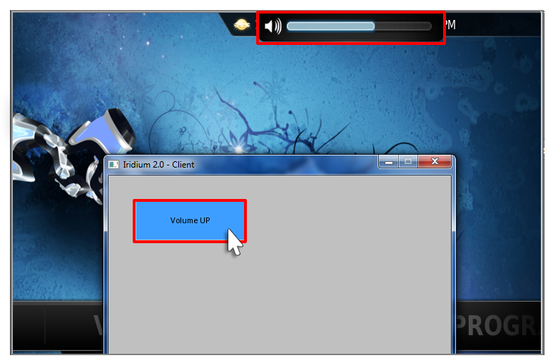
- Turn on XBMC Media Center 11.0 (Eden). Click on the item. The volume will increase.
You can find detailed information about Emulation of project work in the section Emulation of Project Work
Using Channels
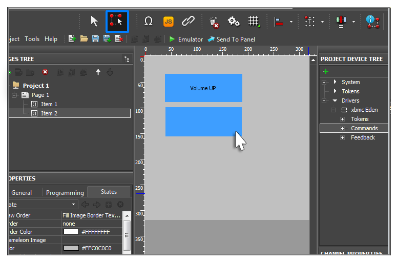
- Create one more graphic item using the Draw Item tool. This graphic item will be used for displaying the current volume level.
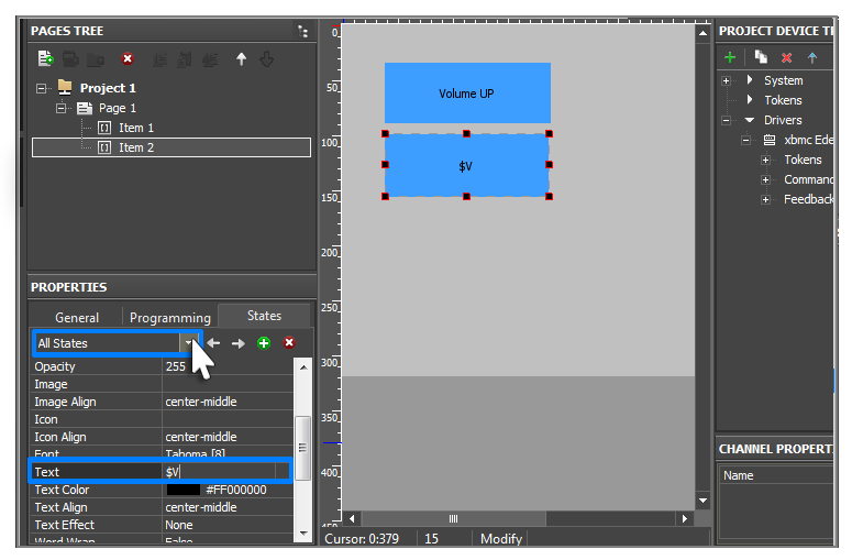
- Go to the tab Object Properties > States.
- By default items have two states. Select All States in the drop-down list. You need to do that for the text you want to write on the item to appear on all item states.
- Find the Text field and write $V in it.
$V is one of the templates for processing and outputting values on graphic items. It is used for displaying the current value (Value) of the item.
You can find detailed information about using templates in the project in the section
Displaying Status of Variables on Items
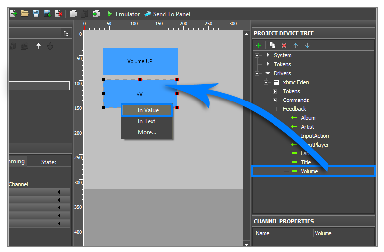
- In order for the graphic item to display the current value of the volume drag the Volume channel on it using the Drag&Drop method. Select the In Value value in the appeared window. As a result when Emulator is working the $V template will be replaced by the current channel value.
Checking the Work of the Channel
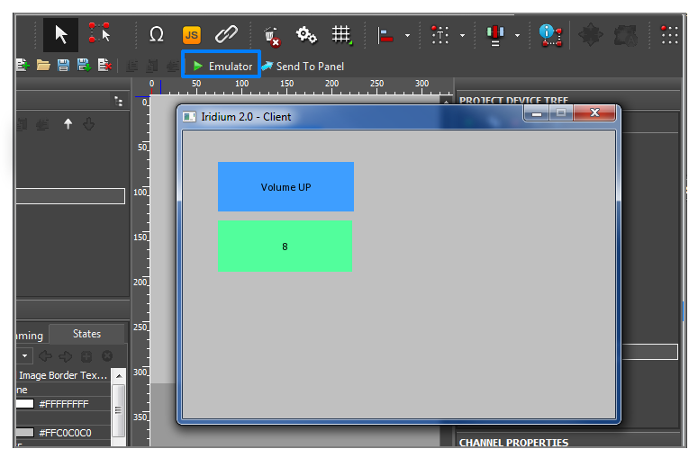
- Launch Emulator; Emulator window will open together with your project.
- Turn on XBMC Media Center 11.0 (Eden) if it is off. The current volume will be displayed.

