Working with Equipment
Contents
- 1 Tools for Working with Controlled Equipment
- 2 Adding New Devices
- 3 Tokens – Variables of the Project Device Tree
- 4 Settings for Connection to Equipment
- 5 Creating Commands and Status Channels
- 6 Relations between Commands, Channels and the Project Graphic Part
- 7 Macros for Equipment
- 8 Displaying Status of Variables on Items
- 9 Notifications about System Events
After finishing the graphic part of the project it is required to create, set up and relate to the interface the driver part of your iRidium project. The driver part of the project includes information about connection to the controlled equipment and settings for communication with the equipment represented by commands and status channels placed in one tree.
Tools for Working with Controlled Equipment
You can set up the project driver part in the “Device Panel”, “Project Device Panel” Editor tabs and in the “Properties” tab.
Device Panel – the iRidium data base of all iRidium supported native and script drivers and also devices and commands which help to control various automation via TCP/IP, UDP, RS232, IR, HTTP.
Project Device Panel – contains devices you need to control in the particular iRidium project, tokens (global variables) and system variables for receiving data from the control panel without involving the controlled equipment.
Properties – the tab of settings for connection to the controlled equipment, commands and channels of the controlled equipment.
Drivers are added to the project tree from iRidium Device Base by the Drag&Drop method. When a driver is added you can set up settings of connection to the equipment to be communicated by the driver.
After the connection setting set up commands and status channels which define methods of communication with the equipment. The commands and channels are assigned to graphic items for activation of data sending or they can be activated by scripts.
Adding New Devices
iRidium Device Base contains information about all native and script iRidium drivers which enable you to control various automation equipment, Audio/Video systems, etc. To use a native driver in your project drag in from iRidium Device Base to the Drivers category of the Project Device Panel tree:
Each device has three types of channels grouped in device folders:
- Tokens
- Commands
- Feedback
Commands
Commands - commands formed with the help of the driver native part or manually with script drivers. They are sent to the controlled equipment.
Feedback
Feedback - variables for receiving and storing data received from controlled equipment
Tokens – Variables of the Project Device Tree
Token is a special type of variables in the iRidium project device tree which does not refer directly to the controlled equipment.
There are 3 types of tokens:
- System Tokens – system variables. They can only read data and receive various parameters of controlled devices: system time, battery status, etc. System Tokens
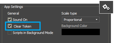
- Project Tokens – project variables. They can read and write data. You can write any value or text from drivers or items in a token and then use it in the project. Tokens are not cleared at the start of the project if you do not mark the Clear Token, box which is in the System tab of Project Properties.
- Driver Tokens – driver variables. They can only read data and receive various parameters of the driver: the connection status, host and port of the controlled driver, etc.
System Tokens
System Tokens are system variables located in Project Device Panel. They receive values of OS parameters and the device the project runs on.
A system token can be assigned to any graphic item of the interface and the information received from the token will be output in the interface. You cannot write values from the interface in the system token as only the system can enter data to the token.
You can find more information about system tokens and their activation from scripts in the article:
System Tokens
Project Tokens
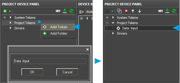
Project Tokens are project variables. They can store data which are available for reading and writing. Writing of data to tokens and reading of data can be performed by graphic items, drivers or scripts.
- Token are stored in the project device tree (Project Device Panel)
- You can write numbers or strings to tokens (DEC or ASCII).
- Tokens can be created, removed, copied, sorted and grouped in folders.
- Data in tokens can be saved (or might not be saved) after closing the iRidium application.
- You can write data to tokens with the help of commands from items, drivers or iRidium Scripts
You can write data to Project Tokens with the help of the macro group Send to Token in Macros Editor of graphic items
- Send Number – write a decimal number in the token (the DEC format)
- Send Text – write text in the token (the ASCII format)
- Send Token – write data taken from graphic item properties in the token (Value, coordinates, size, etc. – variable values defined by the object properties)
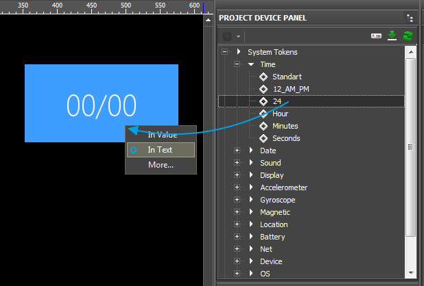
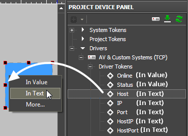
You can read data from Project Tokens by dragging Tokens on graphic items:
- In Text – writing the token value in the item Text property. The data will be displayed on the item depending on their type (a string or a number).
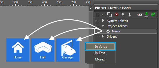
- In Value - writing the token value in the item Value property. The graphic item will take the state (beginning with zero) depending on the number the token has. In this case the token is required to have a number.
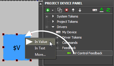
- If you write the template of value output $V in the item Text property, the token value will be also displayed on the item.
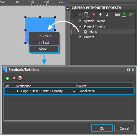
- More – writing the token value in the random property of the graphic item selected by the user. In this case the token is required to have a number.
- For example, the value of the Menu project token has to be written in the item Opacity property:
- Project Tokens can store data after closing the iRidium application.
- If it is required for Project Tokens to cear their values after closing the application, go to Project / Project Properties / System and mark the Clear Token property.
Typical tasks:
- relations between buttons without using drivers (equipment) or scritps
- creation of the Radio Buttons menu
- the project demo mode (commands and feedback channels are not assigned to real equipment)
- storing useful data between project launches
Example: Setting up project navigation menu using Radio Buttons
Example of creating the navigation menu with the help of Project Tokens (communication of Buttons will be performed as follows: only one of the items can be active at a time):
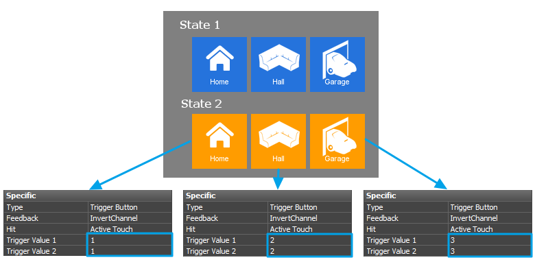
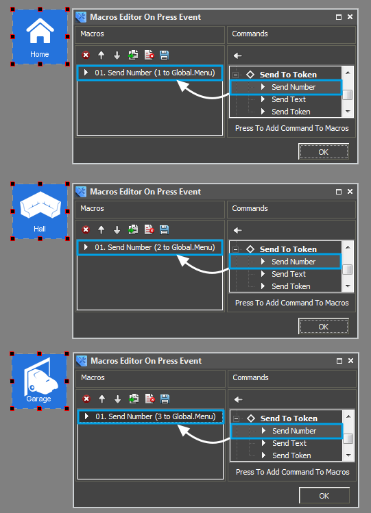
- Create three graphic items and set up the following properties in the Programming tab of the Object Properties panel:
- Create the Menu token and drag it to the graphic item selecting In Value.
- For each graphic item create the Send Number macros writing the sequence number of the graphic item (1, 2, 3) in the Menu token.
Download:
Example of using Project Tokens for Windows, iPhone, iPad >>
Driver Tokens
Driver Tokens – global variables storing general properties of the controlled equipment. These properties can be read only not changed. To use a token drag it to the graphic item as a feedback channel (the token value can be output in the item text field or it can be used to change the item state)
| Online | a state of connection to the controlled system (Online/Offline = 1/0) |
| Status | the status of connection to the system (Offline/Connect/Online/Disconnect = 0...3) |
| Host | a domain name of the remote system |
| HostPort | a port of the remote system iRidium App is connected to |
| IP | an IP-address of Control Panel |
| HostIP | an IP-address of the remote system iRidium App is connected to |
| Port | a local Client port which the connection to the remote device is established through |
Settings for Connection to Equipment
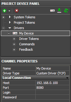
When the driver is added it is required to select it in the device tree and go to the Properties tab which contains settings of tree components. Here you indicate the settings for connection to the controlled equipment with the help of the driver:
The Properties tab contains settings for local and external connection to the control equipment. In other words, you can set up properties of connection to the equipment both when the control device is in one IP-subnetwork with the automation object and when the equipment is controlled via the Internet:
| Name | a name of the controlled device (at random) |
| Driver Type | a type of the driver which helps you to control the device (unchanged) |
| Local Connection | a section for setting connection to the equipment in the local network of the automation object |
Creating Commands and Status Channels
Command and status channels serve for defining ways of communication to the controlled equipment on the basis of a standard driver. You can create an unlimited number of commands and channels for one device in the project. Usually the number of commands and channels is defined by the number of controlled equipment units, the number of commands it is required to send and the number of units which status should be displayed in the iRidium project.
To create commands use tools of Project Device Panel which allow you not only to create new commands or channels but also to import data from the project file or scan the network (for some equipment types). There are the following ways of creating commands and channels when working with various iRidium drivers:
- 1. Creating commands and channels manually
You can create a command or status channel with the “Add Command” tool of Project Device Panel:
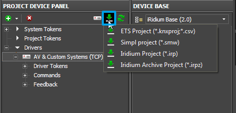
- 2. Importing data from projects
If iRidium supports data import from configuration projects controller you need to communicate with, you can add all controlled units from controller configuration project to your iRidium project. At the moment iRidium supports data import from the following files:
- iRidium Project (*.IRP, *.IRPZ) – import of devices from iRidium projects
- ETS Project (*.pr3, *.pr4, *.pr5, *.knxproj, *.csv) – import of group addresses from ETS projects (for KNX)
- Simpl project (*.smw) – import of joins from Crestron projects
- 3. Scanning the local network for devices
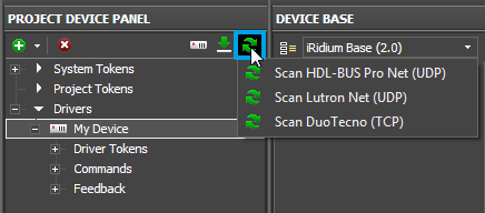
There is a toll for scanning the local network of the automation object for some types of equipment. It allows you to find devices responded to iRidium by a particular protocol and add them to the Project Device Panel tree. These devices can have preset commands and channels, connection settings and infrastructure including the object network.
At the moment iRidium supports scanning for the following types of devices in the local network:
- HDL-BUS Pro Net (UDP) – equipment using the HDL-BUS Pro protocol
- Lutron (UDP) – equipment using the Lutron protocol
- DuoTecno (TCP) – equipment using the DuoTecno protocol
Relations between Commands, Channels and the Project Graphic Part
After setting up the equipment it is required to set up relations between the graphic and driver parts of the iRidium project. The relations are set by assigning commands and channels to graphic items of the iRidium project.
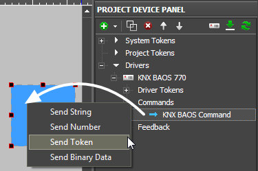
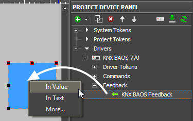
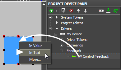
To assign a command or channel to a graphic item use the Drag&Drop method – drag the tree object to the project graphic item. At that you will see the window where it is required to indicate the way of communication between the item and the command. Settings of graphic items directly affect ways of data sending, receiving and displaying.
For example, when working with the Custom (TCP) driver you can send data only from the command information field (Send Command) but you can display data received from the equipment in several ways (output it in the text field, change the item state).
Ways of data sending and processing are defined by the type of the controlled equipment driver.
Macros for Equipment
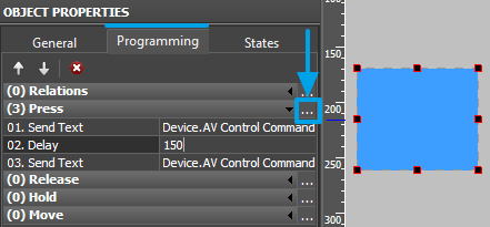
With the help of macros you can create sequences of data sending and scenarios for controlling equipment. Macros can contain sequences of outgoing data, delays between data sending and commands for graphic interfaces. Macros are created in the Programming tab of graphic items and can be set for various interface and system events.
The window for macros creation is described in detail in the Macros (Macros Editor)section.
Displaying Status of Variables on Items
There are two ways to output the value received from the controlled equipment on graphic items:
- 1. Output the received value in text as it is
If the value received from the controlled variable does not have to affect graphic item states and is used for displaying in the graphic item text field only, select “In Text” when assigning the status channel to the graphic item. It will enable the variable to affect only the text field without changing the item state:
- 2. Process (convert) and output the received value in text
When it is required to process the received data, for example, display the absolute value in the percentage terms, the templates of processing and outputting values on graphic items are used. To use the templates the status channel should be assign to the graphic item “In Value”.
Template |
Function |
Template |
Function |
$P |
Output of the current level value in percentage | $V |
Output of the current value |
$L |
Output of the lower level value | $H |
Output of the upper level value |
$S |
Output of the current state number | $A |
Output of the current value minus the lower level value |
$R |
Output of the level range (Upper level value minus lower level value) | $F1-5 |
Output of the value with a floating point, number of symbols after a point |
$X |
Output of the current value in the hex type | $$ |
Output of the "dollar" symbol |
A command (template) of incoming data processing and displaying is entered into the text field of a graphic item and can be combined with other text or symbols (comments, units of measurement)
Templates are written in the item text field and are substituted by the converted data. You can use any text blocks with templates too (measurement units, comments).
Notifications about System Events
Notification is a message, sound or action which informs a user about changes in the system. Notifications work when "i2 Control" is opened on the control panel. They are set up with the help of iRidium Script and can perform any actions and combinations of actions available in iRidium Script.
At the moment notifications for the background mode (minimized or closed application) are not supported.
As a notification you can:
- show a text message on a graphic item;
- show a page or a popup with notification
- play a sound;
- activate a command for the controlled system automatically (turn on/off lights, switch off the radio when receiving an Intercom call, etc.)
With the help of iRidium Script you will be able to form the list of any conditions and actions which you need to perform when the conditions are satisfied.
Example of use:
- show the Intercom dialog window when receiving the incoming call;
- show the notification when the leakage sensor is activated.
Setting up notifications:
- 1. Create a visualization project, set up its user interface and work with drivers (in accordance with instructions for your equipment)
- 2. Create a script file (Ways of Creating and Launching Scripts)
- 3. Form handlers for driver events at which notifications should appear in the script file.
See a few examples of notifications below.
1. Notify about connection to equipment (Online)
- Event:
- successful connection with equipment ("My Driver"). “Equipment” – any driver of the visualization project.
- Action:
- output text information about the event (for example, " System Online") and time of event initiation in the 24-hour format ("System.Time.24") on the graphic item ("Item 1") located on the page ("Page 1"). Change the color of the output text to green.
- Example::
/***** online notification ****/
IR.AddListener(IR.EVENT_ONLINE, IR.GetDevice("My Driver"), function()
   {
       IR.GetItem("Page 1").GetItem("Item 1").Text = IR.GetVariable("System.Time.24") + " System Online";  // notification
       IR.GetItem("Page 1").GetItem("Item 1").GetState(0).TextColor = 0x00FF00FF;  // text color
   });
2. Notify about disconnecting from equipment (Offline)
- Event:
- disconnection from the equipment ("My Driver"). “Equipment” - any driver of the visualization project.
- Action:
- output text information about the event (for example, " System Offline") and time of event initiation in the 24-hour format ("System.Time.24") on the graphic item ("Item 1") located on the page ("Page 1"). Change the color of the output text to red.
- Example::
/***** online notification ****/
IR.AddListener(IR.EVENT_OFFLINE, IR.GetDevice("My Driver"), function()
   {
       IR.GetItem("Page 1").GetItem("Item 1").Text = IR.GetVariable("System.Time.24") + " System Offline";  // notification
       IR.GetItem("Page 1").GetItem("Item 1").GetState(0).TextColor = 0xFF0000FF;  // text color
   });
3. Automatic opening of the popup when activating a channel
- Event:
- receiving values (1 and 2) from the channel ("Channel 10") of the driver ("My Driver"). “Equipment” - any driver of the visualization project.
- Action:
- 1. When receiving 1 – open the popup ("Popup 1"), output event information (for example, " Lamp in Garden broken") and time of event initiation in the 24-hour format ("System.Time.24") in the text field ("Item_Display") of the popup.
- 2. When receiving 2 - open the popup ("Popup 1"), output event information (for example, " Lamp in Garden Response Failed. Please Check") and time of event initiation in the 24-hour format ("System.Time.24") in the text field ("Item_Display") of the popup.
- Example::
/***** event notification (Tag Change) ****/

var old_value1 = -1;   // do not show notification if the previous state is the same
var old_value2 = -1;

IR.AddListener(IR.EVENT_START, 0, function()
{
   IR.AddListener(IR.EVENT_TAG_CHANGE, IR.GetDevice("My Driver"), function(name, value)
{
     if (name == 'Channel 10' && value == 1 && value != old_value1) // Check the Value = 1 in Feedback "Channel 10"
   {
      IR.ShowPopup("Notify_danger");
      IR.GetItem("Popup 1").GetItem("Item_Display").Text = IR.GetVariable("System.Time.24") + " Lamp in Garden broken";
      old_value1 = value;
   }
     else if (name == 'Channel 10' && value == 2 && value != old_value2)              // Check the feedback "Channel 10'"
   {
      IR.ShowPopup("Notify_important");
      IR.GetItem("Popup 1").GetItem("Item_Display").Text = IR.GetVariable("System.Time.24") + " Lamp in Garden Response Failed. Please Check";
      old_value2 = value;
   }
});
4. Play a sound at channel activation
- Event:
- receiving any value (1) from the channel ("Channel 11") of the driver ("My Driver"). “Equipment” - any driver of the visualization project.
- Action:
- 1. When receiving 1 – play the notification sound and output event information (for example, " Incoming Call") and time of event initiation in the 24-hour format ("System.Time.24") in the text field of the graphic item ("Item 5 ") on the ("Page 1").
- Example::
/***** event notification (Tag Change) ****/
IR.AddListener(IR.EVENT_START, 0, function()
{
   IR.AddListener(IR.EVENT_TAG_CHANGE, IR.GetDevice("My Driver"), function(name, value)
{
     if (name == 'Channel 11' && value == 1) // Check the Value = 1 in Feedback "Channel 11"
   {
      IR.PlaySound('BEEP1.WAV',1,70); // Play Sound ('name',slot,volume)
      IR.GetItem("Page 1").GetItem("Item 5").Text = IR.GetVariable("System.Time.24") + " Incoming Call";
   }
});
Download: example of notifications for KNX: simple notifications, the notification center

