Global Cache: Control via RS232
Contents
- 1 Principles of Controlling Equipment via RS232
- 2 Setting up Global Cache
- 3 Setting up of Global Cache Modules in iRidium
- 4 Creating Commands for Global Cache (Serial)
- 5 Sending Global Cache Commands from Graphic Items
- 6 Creation of Your Own Base of Global Cache (RS232) Commands
- 7 Switching Between the Local and Internet Connection
- 8 Downloads
Global Cache (GC-100-06, GC-100-12, iTach IP2IR, iTach WF2IR) is a family of converters for controlling audio-video equipment. They receive commands via TCP/IP and send them to the controlled equipment as IR signals or via the СОМ-port. Converters can send commands in the local network or via the Internet. There are preset Global Cache drivers in iRidium.
Conditions for working with equipment through Global Cache:
- possibility to control the selected equipment via RS232
- commands for controlling equipment via RS232
Description of driver work:
iRidium for Global Cache supports connection to Global Cache converters via TCP/IP. Commands for sending via RS232 have the fixed format (syntax) and can be sent after connection to the converter.
The feedback from the Global Cache converter can be processed with the help of iRidium Script.
![]() iTach converters support up to 4 connections. GC-100-06(12,18,18R) converters support only 1 connection. Feedback from equipment is sent to all iRidium panels. The mode of multiple connections can be activated or deactivated via the iTach web-interface.
iTach converters support up to 4 connections. GC-100-06(12,18,18R) converters support only 1 connection. Feedback from equipment is sent to all iRidium panels. The mode of multiple connections can be activated or deactivated via the iTach web-interface.
Principles of Controlling Equipment via RS232
In iRidium you can use Global Cache modules to control your Audio-Video and other equipment via RS232:
Connection to Global Cache: TCP/IP.
Global Cache outputs: RS232
RS232 command formats: ASCII, HEX, DEC.
Feedback from equipment: with the help of iRidium Script, see iRidium DDK and iRidium Script API.
Required licenses: "Device License Pro for AV & Custom Systems" or "Site License Pro for Global Cache" (see Licensing). They work with Global Cache and any AV equipment. It enables use of any scripts in your projects.
Setting up Global Cache
In order for iRidium to connect to a Global Cache (GC) converter, the converter has to be set up for work in one IP network with iRidium. Information about GC setting up:
Video-lessons on setting up Global Cache converters
Documentation and a set of programs for Global Cache converters
Types of Global Cache Converters with the RS232 Support

|
iTach WiFi to SL (Serial, WF2SL)
|

|
iTach TCP/IP to SL (Serial, IP2SL)
|

|
GC-100-06, GC-100-12, GC-100-18, GC-100-18R
|
Setting up СОМ-ports of Global Cache
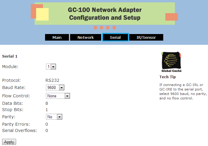
You can set up the СОМ-port in the GC web-interface, select the Serial tab.
Setting properties depend on requirements of controlled equipment:
To open the Global Cache web-interface, use iHelp and "Quick Start Guides".
Setting up of Global Cache Modules in iRidium
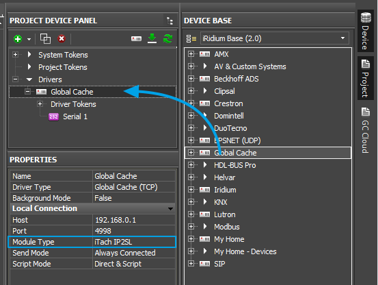
Select the Global Cache driver in the DEVICE BASE list of iRidium GUI Editor and drag it into the PROJECT DEVICE PANEL window:
Properties of connection to Global Cache:
- Host – the IP-address of the converter (local, external or the domain name)
- Port – the main port of connection with GC (4998). It is used for sending IR commands, setting up and receiving the Global Cache status.
- Module Type – the type of the Global Cache converter: GC-100-06, GC-100-12(18,18R), iTach IP2IR (WF2IR), iTach IP2SL (WF2SL), iTach IP2CC (WF2CC). It defines the number of converter outputs and their type.
- Send Mode – the mode of connection to the converter
- Always Connected – constant connection (standard mode)
- Connect when Sending – connection only for command sending. It is meant for GC-100-06(12,18,18R) to which you need to connect several control panels
- Confirm IR – to send the IR command only after confirming the sending of the previous one. It helps to avoid overlapping of IR commands.
- Script Mode – it defines where to send commands
- Direct and Script – to send the command to the converter right away and duplicate it in the script (data can be processed in iRidium Script)
- Script Only – to send the command to the script only (when clicking the button the command will not be sent to the converter). It enables sending of command components to the scripts to drivers work. Do not activate this mode if you do not use scripts.
When working with GC-100, you have to set up properties for working with IR outputs, see Global Cache: Control via IR.
To connect to equipment via the Internet:
- 1. Indicate the public IP-address (or the domain name) of your Internet router in the Host field
- 3. Set up Port Forwarding on your router to enable remote control of your equipment .
- You can learn the public IP-address of your router with the help of external resources, for example [1]
To switch between local and Internet connection:
Use the example presented below.
Setting up of Global Cache COM-ports in iRidium
Global Cache СОМ-ports are not set up in iRidium. All RS 232 properties have to be indicated with the help of Global Cache web-interface. There is a possibility to change the connection port (4999 = СОМ1, 5000 = СОМ2) for working with GC-100 through iRidium Gate.
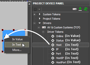
Driver Tokens
Driver variables are available for reading only. They help to monitor connection to equipment.
| Online | the state of connection to the controlled system (Online/Offline = 1/0) |
| Status | the status of connection to the system (Offline/Connect/Online/Waiting = 0...3) |
| Host | the domain name of the remote system |
| HostPort | the port of the remote system to which iRidium App connects |
| IP | the IP-address of the control panel |
| HostIP | the IP-address of the remote system to which iRidium App is connected |
| Port | the client local port through which connection to the remote device is performed |
Creating Commands for Global Cache (Serial)
Select the commands you need to send through Global Cache. They can be stored in one of the following formats:
- ASCII - string
- HEX – hexadecimal
- DEC - decimal
You need to prepare the information which is stored in one of these formats correctly so iRidium could process it and send to the equipment. Use iRidium "syntax" for forming commands.
Commands in the ASCII Format (Strings)
Add a ASCII string in the "Data" window on the Serial output:
- include it in ‘single quotes’.
- if the string is followed by data in a different format, separate them with commas
- use the "carriage return" <CR> and "line end" <LF> symbols in the end of the string
| Initial command (in documentation): |
PWR01 <CR> | VOLUME 50 <CR> <LF> | AUD 1>3 <CR> | 6CH/8CH <CR> <LF> |
| In iRidium (the Data field): |
'PWR01',0x0D | 'VOLUME 50',0x0D,0x0A | 'AUD 1>3',0x0D | '6CH/8CH',0x0D,0x0A |
The "carriage return" <CR> and "line end" <LF> symbols:
| In documentation: | <CR> | <CR> | <CR> | <LF> | <LF> | <LF> |
| In iRidium (the Data field): | 0x0D | $0D | 13 | 0x0A | $0A | 10 |
You can use any of the 3 variants for indicating the line end.
Commands in the HEX (Hexadecimal) Format
Add HEX data in the "Data" window on the Serial output:
- write $ or 0x before each HEX symbol
- do not use blank spaces, divide HEX symbols with commas
- if there are additional symbols near HEX symbols in your documentation, remove them (FFh > FF)
- use the "carriage return" <CR> and "line end" <LF> symbols after the last HEX symbol
| Initial command (in documentation): |
01 81 81 81 <CR> | 16 8A FF <CR> <LF> | 19h EEh A1h <CR> <LF> |
| In iRidium (the Data field): |
0x01,0x81,0x81,0x81,0x0D | 0x16,0x8A,0xFF,0x0D,0x0A | 0x19,0xEE,0xA1,0x0D,0x0A |
The "carriage return" <CR> and "line end" <LF> symbols:
| In documentation: | <CR> | <CR> | <CR> | <LF> | <LF> | <LF> |
| In iRidium (the Data field): | 0x0D | $0D | 13 | 0x0A | $0A | 10 |
Commands in the DEC (Decimal) Format
Add DEC data in the "Data" window:
- do not use additional symbols
- do not use blank spaces, divide symbols with commas
- use the "carriage return" <CR> and "line end" <LF> symbols after the last number
| Initial command (in documentation): |
01 255 255 <CR> | 20 30 40 50 <CR> <LF> |
| In iRidium (the Data field): |
01,255,255,13 | 20,30,40,50,13,10 |
The "carriage return" <CR> and "line end" <LF> symbols:
| In documentation: | <CR> | <CR> | <CR> | <LF> | <LF> | <LF> |
| In iRidium (the Data field): | 0x0D | $0D | 13 | 0x0A | $0A | 10 |
Sending Global Cache Commands from Graphic Items
Create a visualization interface.
The interface can be created from scratch or you can use a ready solution. It can contain interfaces of any appearance. Commands for equipment are not linked to interface items by default.
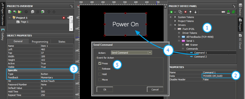
Example of sending commands:
- 1. Add the Global Cache module in your iRidium project. Set up properties of connection to it.
- 2. Create a command. Indicate data for sending to equipment in the Data field on the Serial output.
- 3. Set up the button which will be responsible for sending the command.
- Type: Button
- Feedback: Momentary
- 4. Drag the command on the button.
- 5. Select the event on which the command will be sent:
- Press – pressing on the item
- Release – releasing the item
- Hold – holding the item
- Move – moving on the item (it is mainly used for Level)
![]() You cannot change the command in the Data field when the project is already uploaded on your control panel. It means that if your command, for example, is responsible for setting the volume to 50%, it cannot be assigned to Level for gradual volume regulation. It will work only with Button and set the volume to 50% at each pressing.
You cannot change the command in the Data field when the project is already uploaded on your control panel. It means that if your command, for example, is responsible for setting the volume to 50%, it cannot be assigned to Level for gradual volume regulation. It will work only with Button and set the volume to 50% at each pressing.
![]() To send values (e.g. volume) from Level, you need to from the command with the help of scripts (see iRidium Script API and iRidium DDK), not in the project tree.
To send values (e.g. volume) from Level, you need to from the command with the help of scripts (see iRidium Script API and iRidium DDK), not in the project tree.
Set up command sending on clicking on interface items.
Assign commands in the project tree with interface graphic items to send commands when clicking the items.
Events at which commands can be sent:
- Press – pressing on the graphic item
- Release – releasing the graphic item (after pressing)
- Hold –holding the graphic item (in cycles, as long as the item is not released)
- Move – moving on the item (it is mainly used for Level)
Events at which commands can be sent from scripts (they are not described in the present section, see iRidium Script API):
- receipt of feedback with a particular value
- pressing on/releasing interface items
- timer expiration
- receipt of particular values from the panel sensors (GPS, accelerometer, gyroscope, ..)
Ways of command sending from interface items:
- Sending a single command when pressing on (releasing) the button
- Sending a macro – a sequence of IR commands when pressing on (releasing) the button
- Sending a command in cycles on holding the item
You can find description of the ways of sending commands below.
Sending IR Commands When Pressing on (Releasing) Button
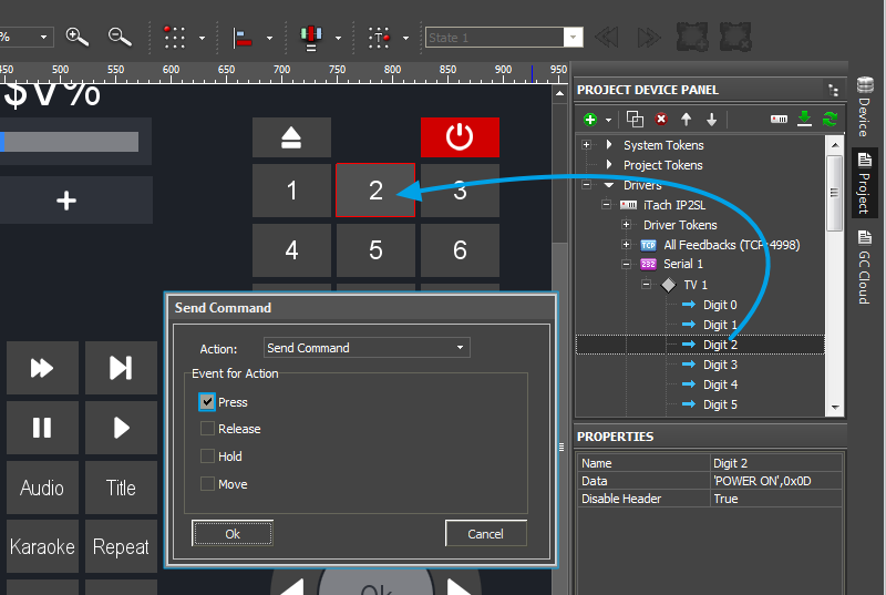
Drag a command it to the graphic item which will initiate the command sending:
Select the event of command sensing in the Send Command dialog window:
- Press – pressing the item
- Release - releasing the item
- Hold - holding the item
- Move – moving on the item (mainly for Level type items)
The Press event is indicated by default as it is the most frequently used one.
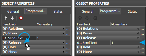
You can see added commands of the item in Object Properties >> Programming.
* it is required to drag the command by its text (name)
Sending Macros – Sequences of Commands
Macro – it is several commands which are sent one by one after clicking one button. A macro command can activate GC commands, commands to another equipment, timeouts, commands to pages, etc.
 Important! The controlled equipment can hang if the commands are sent too often. To avoid the overload of the equipment, you should send the commands with the interval considering the time for their execution. The length of the interval is defined by test, it can be +/- 50..300 ms.
Creating macro comands:
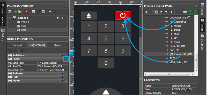
- 1. Create a button for activating a macro command.
- 2. Drag all commands you need to be sent onto it.
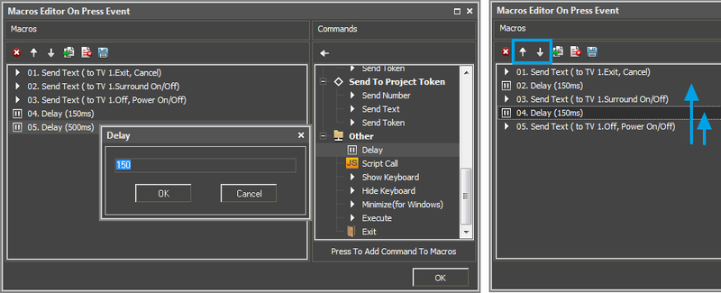
- 3. Open Macro Editor of the Press (or Release) event where you dragged their commands
- 4. Put the IR command in order for sending with the help of arrows (execution: top-down)
- 5. Select the Delay command (the Other folder) and add the required number of delays (on the number of intervals between the commands)
- 6. If the macro command has to execute more actions, then put them in the order of execution.
Sending Commands on Hold
Hold – the event of "holding the item". It activates the cyclic sending of commands written in the macro of the Hold event. On Hold It is possible to send one or several commands in a cycle. The cycle stops when releasing the item or activation of Move.
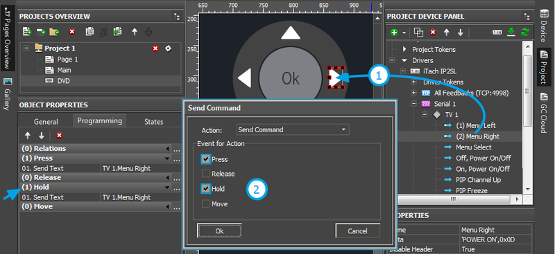
Setting up the Hold event:
- 1. Drag the command on the graphic item
- 2. Mark the Hold event.
In the example you can see that the Press event is activated as well. It is done so the item reacted both on its holding and clicking.
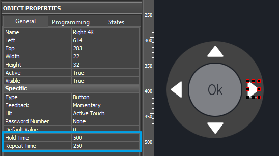
- 3. Set up the properties of the Hold event in Object Properties >>> General
- Hold Time (ms) – the time after which the Hold event is activated when holding the item
- Repeat Time (ms) – the interval of repeating commands from the Hold macro.
The commands written in the Hold event will be sent in a cycle until the button is held with the interval indicated in Repeat Time.
Control from Levels, Trigger Buttons and Other Items
When working with GC without feedback, it is not possible to set up sending of two commands one after the other or sending volume commands from Level in a standard way. It is due to the fact that an IR command contains a target action and you cannot change it while the project is working .
In order to send two commands in turns or to create a complex sequence of command sending you should use iRidium Script. It is a built-in programming language which enables relating IR commands and their sending. See iRidium Script API.
Creation of Your Own Base of Global Cache (RS232) Commands
To use RS232 commands in any iRidium project you need to save it in the iRidium data base.
Use DB Editor for adding devices. New devices can be added only to custom data bases as standard data bases cannot be edited.
![]() Creation of data bases is not the only way of transferring commands from one iRidium project to another. If you created a device with commands in your iRidium project, you can import it to another project using File > Import > *.irpz
Creation of data bases is not the only way of transferring commands from one iRidium project to another. If you created a device with commands in your iRidium project, you can import it to another project using File > Import > *.irpz
New Databases
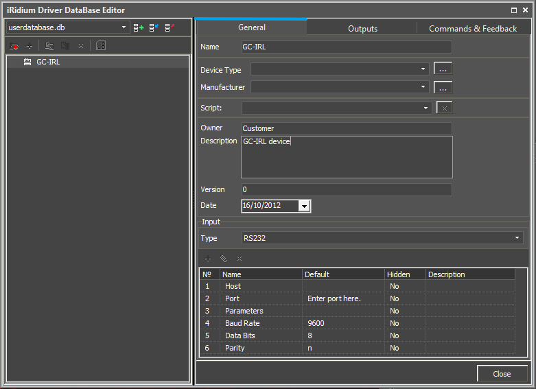
Use custom data bases for storing your devices. They are created in DB Editor. When creating a data base, indicate its name and directory for saving.
Creating new devices:
The type of the created device - RS232 (RS232 Device) – defines its transport part and characteristics.
Setting up devices
Describe new devices to help with their further identification:
- Device Type – the type of the controlled device (TV, DVD, Blu Ray, ...)
- Manufacturer – the name of the device manufacturer
- Description – description of the device, it can include hyper links
- Date – the date of creating the driver
Properties for connection:
- Port – the number of the СОМ-port to which the controller is connected
- Baud Rate – the speed of data exchange
- Data Bits – the number of information bits in a frame
- Parity – control of parity
- Stop Bits – the stop bit in a frame
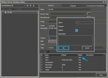
Optional properties:
- Parameters – additional properties for connection
- Login
- Password
The optional properties can be hidden: click two times on the property to open the window for settings and select Hidden.
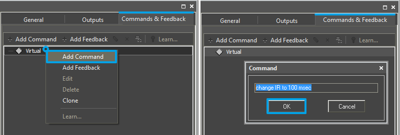
Adding commands in the list of devices
Go to the Commands & Feedback tab and use tools of iRidium GUI Editor:
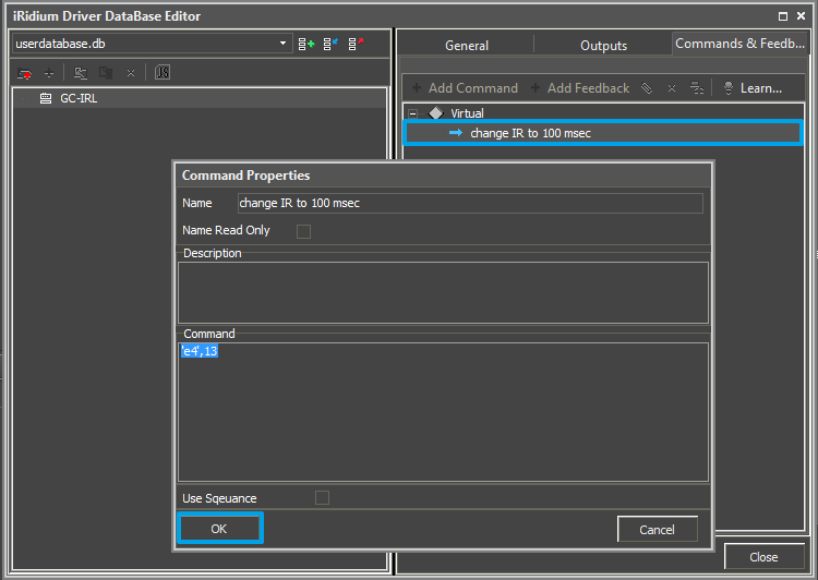
The command is empty by default. The instruction the command should send is indicated in the Command Properties window. Click two times on the created command to open the Command Properties window.
- Write the instruction for the command in the Command field of the opened window. In our case for the Reset command (device resetting) there is the 'e4',13 instruction, where e4 is the instruction content, 13 = <CR> (the command is sent in the ASCII format).
- Mark the Name Read Only field if you do not want to change the command name in the future (it is used when the driver works with scripts which refer to the command identifying it by its name).
- In the Descriptions field indicate the command description.
When all commands are added, save the database.
![]() Devices from the database can be added on the Serial output of Global Cache. At that the connection settings created in the database are not considered.
Devices from the database can be added on the Serial output of Global Cache. At that the connection settings created in the database are not considered.
![]() To add a device from the database to the Serial output of Global Cache, select your database in the Device Base drop-down list and drag it on the Global Cache output.
To add a device from the database to the Serial output of Global Cache, select your database in the Device Base drop-down list and drag it on the Global Cache output.
Switching Between the Local and Internet Connection
If the control panel should hold the connection with the system when the panel is out of the limits of the Wi-Fi network of the system, you need to set up the switch between the Internet and the local network.
The remote mode suggests connection to the system via the Internet. At that the external IP-address or the domain name of the system to which you need to connect have to be used.
 In iRidium Wi-Fi/3G CANNOT be switched automatically. For switching between the Internet and the local network you need buttons with special settings. See the settings below.
 To control the system remotely you have to open the system for external access -
to set up the Port Forwarding Service.
 To secure equipment from unauthorized access we recommend using secure connection with the remote system (VPN).
Setting up of the switch Wi-Fi/3G in iRidium projects:
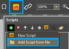
1. Open the script editor in iRidium GUI Editor.
2. Download and add into your project the template of the Wi-Fi/3G switch (Add Script from file):
download the template of the Wi-Fi/3G switch
The Wi-Fi/3G switch is performed with the help of the script function SetParameters
Setting up of parameters of the Wi-Fi/3G switch:
- function Internal_1() // Function name
- {
- IR.GetDevice('Global Cache').SetParameters({
- IR.GetDevice('Global Cache').SetParameters({
Host: "210.110.10.10", // the IP-address of the GC module
Port: 4998, // main connection port
Port1: 4999, // the port of connection to COM1 on GC (if it has COM-ports)
Port2: 5000, // the port of connection to COM2 on GC (if it has COM-ports)
SendMode: 0, // 0 - always connected, 1 - online only to send a command
IrConfirm: 0, // 0 - IR with confirmation, 1 - IR without confirmation
ScriptMode: 0, // 0 - send directly and to the script, 1 - send to the script only
BackGroundMode: 0 // 1 - on, 0 - off
}); // Driver Name + Parameters
- }
- function External_1()
- {
- IR.GetDevice('Global Cache').SetParameters({
- IR.GetDevice('Global Cache').SetParameters({
Host: "210.110.10.10", Port: 4998, Port1: 4999, Port2: 5000, SendMode: 0, IrConfirm: 0, ScriptMode: 0, BackGroundMode: 0});
- }
Indicate in the command settings:
- Function name – the name of the switch function (command). Two functions cannot have the same name in a project.
- Driver Name – the name of the driver which parameters are changed
- Parameters – the set of the switch parameters which you need to apply to the driver
Assign commands to buttons:
- Select the button which will be responsible for the Wi-Fi/3G switch.
Open the properties of the button: Object Properties > Programming - Open Macros Editor of the button for the Press or Release events
- Select the Script Call command and add it by double-clicking on it
- Select the name of the function you want to activate in the drop-down list. Create the command.
Set up access to the equipment from the Internet:
In order to do that open the equipment ports for remote access.
Download the example of the Wi-Fi/3G switch (project) >>

