Basic Operation of iRidium with the KNX Bus Equipment via KNX IP BAOS
Contents
- 1 How It Works
- 2 Preparation of Projects in ETS
- 3 Data Import from ETS
- 4 Setting up the Connection to KNX IP BAOS
- 5 Switching Local and Public IP-addresses of KNX IP BAOS
- 6 Principles of Communication with the Equipment of the KNX Bus via KNX IP BAOS
- 7 Emulation of Project Work
- 8 Launching Projects on Control Panels
How It Works
To connect to the KNX bus iRidium Apps use the Object Server protocol of KNX IP BAOS routers and TCP transport. Sending and receiving data is possible if the control device and KNX IP BAOS interface are located in one IP-subnetwork.
Topology of communication between iRidium Client and the equipment of the KNX bus through the KNX IP BAOS interface:
Preparation of Projects in ETS
Setting up of BAOS (Object Server) is performed in ETS where ready group addresses are related to datapoints – KNX IP BAOS intermediate addresses. Most important details about programming group addresses in ETS are described here.
Set up connected between KNX group addresses and BAOS objects - intermediate addresses (datapoints).
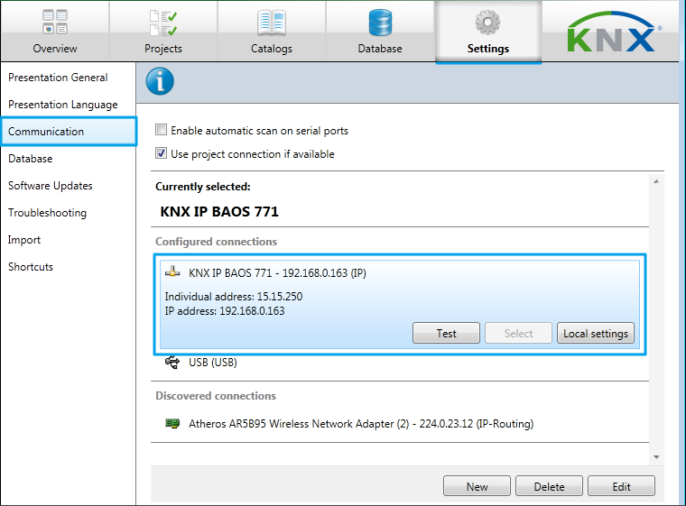
1. In order to start the setting up add the KNX IP BAOS interface in the list of connections of ETS and select it for work:
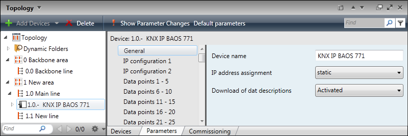
2. Select KNX IP BAOS in the list of devices in the "Topology" window and open the "Parameters" ("Edit Parameters") tab. In the General section indicate the KNX IP BAOS device name and necessity to use the static IP-address (the ТСР protocol and addresses of the IPv4 standard are used for connection to Object Server):
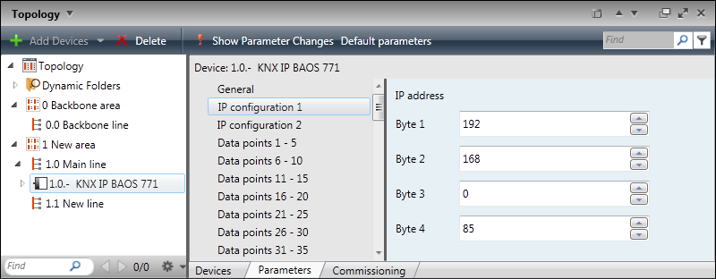
3. Go to the "IP Configuration 1" section in the list of KNX IP BAOS settings and indicate the IP-address of the KNX IP BAOS interface (the subnet mask and gateway address are indicated in the "IP Configuration 2" section by default):
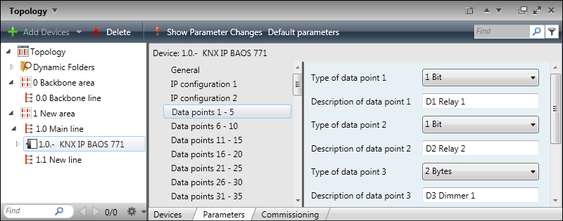
4. Intermediate addresses (datapoints) are activated and set up for connection with project group addresses in the "Data Points n...m" tabs. In datapoint settings indicate the address name and data type it will operate with. Select the same data type as the group address you want to relate to this datapoint:
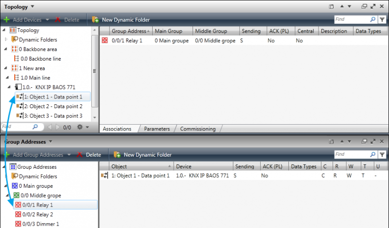
5. Relate the set up datapoint to the corresponding group address(es) by dragging it from the "Topology" window to the "Group Addresses" window:
After all necessary relations are created save the project file in the ETS3 or ETS4 format (*.pr3, *.pr4, *,pr5, *.knxproj, *.csv). Then the project can be imported in the GUI development environment of iRidium GUI Editor for fast setting up of communication with KNX.
Data Import from ETS
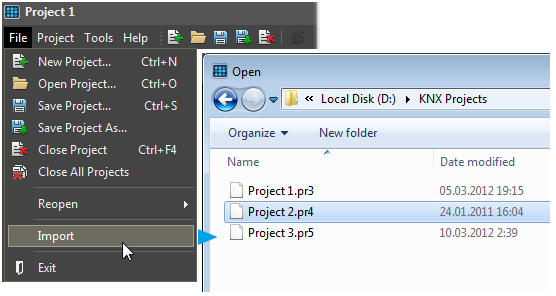
It is possible to retrieve data about existing KNX IP BAOS interfaces and their datapoints from the program of communication with the KNX bus saved in ETS. Data import from the ETS project allows you to set up fast communication with the bus equipment. To take data from the ETS project use the “Import” tool in the “File” menu after creating a new project in GUI Editor:
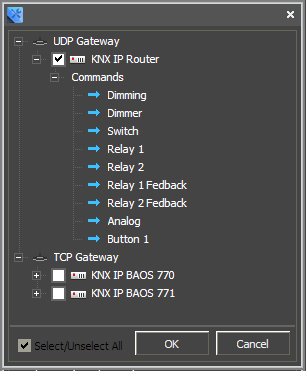
The tool of import from the ETS project forms the list of IP gateways and datapoints for them. You can select the gateways you need to add into your project from the list. As a result of the import you receive Project Device Tree containing imported interfaces and the list of addresses:
If you don’t have an ETS project where you can import the required addresses from, you can create a gateway with datapoints manually. After the import or creating the device manually you can set up the connection and start working with the addresses.
Manual Creation of KNX IP BAOS and Datapoints for Operation with Addresses in the KNX Bus
To refer to group addresses of the KNX bus via intermediate addresses (datapoints) use the TCP protocol. To start work with KNX IP BAOS via TCP it is necessary to add the KNX IP BAOS (TCP) gateway to the project device base. It will use iRidium for sending commands and receiving data from the KNX bus.
Important! "KNX IP BAOS 770" and "KNX IP BAOS 771/772" interfaces use different control protocols and are not interchangeable in iRidium. If you use the "KNX IP BAOS 771" interface you should import it or add it manually to the project base.
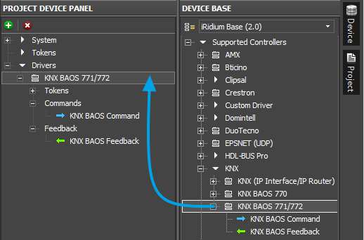
To create the gateway manually select the device based on the KNX IP BAOS (KNX BAOS 770 or KNX BAOS 771/772)protocol in the “DEVICE BASE” window of GUI Editor and drag it into the “PROJECT DEVICE PANEL” window. As a result you receive the KNX IP BAOS gateway. You can use it to send the commands to the KNX bus and receive feedback data with the help of Object Server.
The commands to the bus and feedback channels are created and stored inside the gateway. Activation of command sending and displaying feedback data is performed by communication of commands and channels with graphical items of the interface.
Setting up the Connection to KNX IP BAOS
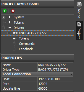
To send commands and receive information from KNX IP BAOS it is required to indicate properties of connection to the BAOS interface in GUI Editor. The TCP network protocol is used for connection of iRidium Apps to KNX IP BAOS interfaces. Connection settings are indicated in the “PROPERTIES” window when selecting the KNX IP BAOS interface in the “PROJECT DEVICE PANEL” window.
In order to send and receive data via KNX IP BAOS it is required to indicate the following properties:
For working with the controller via the Internet indicate the public IP-address of the router the controller is connected to in the connection settings. Port Forwarding Service is set up for the router to enable remote control – referring to the local (private) address of the controlled controller from the Internet.
You can learn the external (public) IP-address of your router with the help of external resources, for example [1]
Switching Local and Public IP-addresses of KNX IP BAOS
To change properties of connection to KNX in the process of project work on the control panel use the method based on using a simple script function (SetParameters).
When it is used:
- it is required to control the automation object via the Internet: switching the local and external IP-interface of the automation system.
- it is required not only to switch between the local and external network but also between several automation objects formed similarly (using one scheme) but located remotely. For example, it can be used for monitoring houses in cottage estates or several offices of one company using typical automation systems.
How to add it in your project:
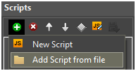
To add the function of changing the connection settings in your iRidium project open the script editor in iRidium GUI Editor.
Add the ready module template with the SetParameters function in your project (Add Script from file) after downloading it from HEREor create a new empty module (New Script):
Set up the function and duplicate it as many times as you need:
function Internal()
{
 IR.GetDevice("KNX BAOS 771/772").SetParameters({Host: "192.168.0.100", Port: "12004", UpdateTime: "0"});
}

function External()
{
 IR.GetDevice("KNX BAOS 771/772").SetParameters({Host: "215.215.10.10", Port: "12004", UpdateTime: "0
}
In the function settings indicate:
- Internal (or External, or another) – the name of the function. Indicate this name in the settings of the button pressing on which will activate the corresponding function. Two functions of one project should NOT have the same name!
- " KNX BAOS 771/772" – the name of the driver in the project tree the function will be activated for.
- Host: "192.168.0.100", Port: "12004", UpdateTime: "0" – the set of properties of connection to KNX IP BAOS which will be used after activating the function.
Activation of the function created with the help of iRidium Script is performed with the Script Call command (Macros Editor). The command should be added for the Press or Release button which changes the properties of connection to KNX.
Go to the macros editor of the button, select the Script Call command and assign it to the button the by double-clicking on it. In the drop-down list you will see the list of the SetParameters functions created by you. Select the function (the set of properties) which corresponds to the button:
>> Download: example of switching local and external settings of connection to KNX IP BAOS
![]() To work with KNX IP BAOS via the Internet indicate the public IP-address of the router KNX IP BAOS is connected to. Set up Port Forwarding for the router to enable remote control – referring to the local (private) address of the controlled KNX IP BAOS via the Internet.
To work with KNX IP BAOS via the Internet indicate the public IP-address of the router KNX IP BAOS is connected to. Set up Port Forwarding for the router to enable remote control – referring to the local (private) address of the controlled KNX IP BAOS via the Internet.
You can learn the external (public) IP-address of your router with the help of external resources, for example [2]
Principles of Communication with the Equipment of the KNX Bus via KNX IP BAOS
When connecting to KNX IP BAOS through Object Server iRidium App can send commands to existing intermediate addresses (datapoints) and receive data from them. To receive data iRidium opens the connection session and waits for changing values stored in the datapoints. KNX IP BAOS sends data about changing values in datapoints without any additional request. iRidium sends requests about changing values in datapoints with a particular frequency (Update Time) to check if there is a connection to BAOS.
To send messages to the bus modules and receive data about status changes of datapoints, create Commands and Feedbacks which correspond to KNX IP BAOS datapoints in your iRidium project. Commands and channels are created on the output of the KNX IP BAOS device they will be sent to the bus through.
Information about datapoints names, addresses and types is imported from ETS projects or indicated manually.
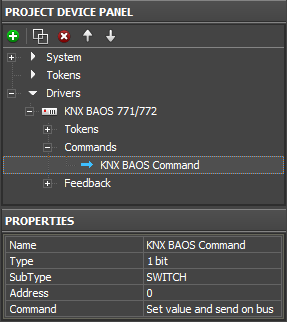
Properties of commands to KNX IP BAOS datapoints (data sending):
| CHANNEL PROPERTIES | |
| Name | a datapoint name, set at random |
| Type | a data type the datapoint operates with |
| SubType | a data subtype (defines the value limits and measurement units) |
| Address | a datapoint address |
| Command | a command type to the datapoint |
Properties of KNX IP BAOS channels (receiving data from datapoints):
| CHANNEL PROPERTIES | |
| Name | a datapoint name, set at random |
| Type | a data type the datapoint operates with |
| SubType | a data subtype (defines the value limits and measurement units) |
| Address | a datapoint address |
The created commands are bound to graphic items of the project. The outgoing instructive values are indicated when binding commands to the graphic items.
In iRidium you can set work with group addresses operating with different data types. The list of supported data types:
| Type: | Value: |
| 1 bit | 0 / 1 |
| 2 bit | 0...3 |
| 4 bit | 0...15 |
| Signed 8-bit | -128 … 127 |
| Unsigned 8-bit | 0 … 255 |
| Signed 16-bit | 0 … 65 535 |
| Unsigned 16-bit | -32 768 … 32 768 |
| Float 16-bit | -671 088,64 … 670 760,96 |
| Type: | Value: |
| Signed 32-bit | -2 147 483 648 … 2 147 483 647 |
| Unsigned 32-bit | 0 … 4 294 967 295 |
| Float 32-bit | 0 … 8 388 607 |
| ASCII string | |
| Time | |
| Date | |
| Date Time |
Control of devices operating with different data types can be performed with the following types of graphic items:
| Button | Sending fixed values; displaying data received from the controller |
| Level | Sending values from the preset range by the slider; displaying the current value by the position of the slider |
| Trigger Button | Switching between two fixed values indicated at the item setting |
| Up/Down Button | Incrementing/decrementing the current value by the preset value in the preset range. The range and the step of increment/decrement are set at the item setting. |
| Multistate Button | Sending fixed values and receiving data accompanied by animation |
| Multistate Level | Sending and receiving values in the preset range where each value or group of values has its own image |
| Edit Box | Inputting a string of data to be sent to the bus |
| Joystick | Controlling RGB with the help of ColorPicker |
There are other types available when setting up graphic items; they are not used for direct sending of values to the KNX bus but serve as visualization objects.
Principles of Sending Commands to the KNX Bus
1. Create a command in Project Device Tree, indicate its name, type, data subtype and group address (command settings can be imported from ETS or set manually).
2. Create a graphic item which is going to initiate command sending to the bus (the item properties depend on the command type and control tasks).
Selection of the item type depends on the required behavior. Selection of the feedback type affects processing and displaying of data received by the channel bound to the item. The main feedback types used:
- Momentary – not to display data received from the channel but change the item state when pressing on it (return to the initial state at releasing it).
- Channel – to display data received from the channel. Data can be output in the item text field; they can affect its state or affect other item properties.
The rest feedback types have specific purposes and are used less frequently.
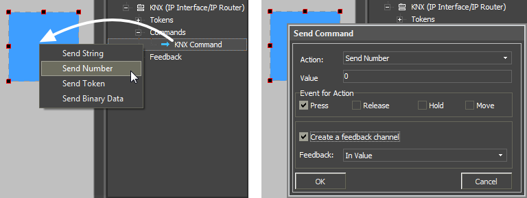
3. Drag the command onto the graphic item (Drag&Drop).
4. When dragging the command the window of selecting general data type, which are sent to the KNX bus, appears:
- Send String – send data strings in the UTF-8 format
- Send Number – send numbers in the decimal format
- Send Token – send values taken by one of the graphic item properties or a global token to the bus (for example you can select sending the current slider position of the Level graphic item)
- Send Binary Data – it is not used for KNX
5. After selecting the general type of data to be sent, indicate the value, variable or string which will be sent to the bus when activating the item.
At the command adding indicate not only the value to be sent to the bus but also the event the value will be sent at in the dialog window:
- Press – pressing on the item (sending telegrams on pressing)
- Release – releasing the item
- Hold – cyclic data sending when holding the item
- Move – sending data at each slider move (all values taken by Level); it is used for the Level item only.
Principles of Receiving and Processing Data from the KNX Bus
- 1. Create a feedback channel for receiving the module status
- (the channel can be created manually, generated in Project Device Tree with the help of the “CreateFeedbacks” button in the right-click menu).
- 2. Drag the feedback channel on the graphic item (Drag&Drop)
- Channel – it is required to indicate this feedback type (Feedback) in the item properties if data of the channel bound to the item affect the behavior of the item (for example, if data from the bound channel has to be output in the text field; or when receiving “1” from the channel the item has to take the second state – change the image).
- 3. Indicate if the value should be output in the item text field, affect its current value or other property:
- In Text – values received from the channel should be output as numbers in the text field
- In Value – values received from the channel should affect the item state (change the slider position of Level, switch Button on/off, initiate animation, etc.)
- More… – select more complex way of communication between the channel and item properties (for example, change item coordinates when the channel value is changed)
Emulation of Project Work
Emulator
- is an iRidium application for Windows which can be launched from GUI Editor for testing your projects. Emulator can work both with a license (with connection to the equipment) and without it (when only the project graphic part is functional).
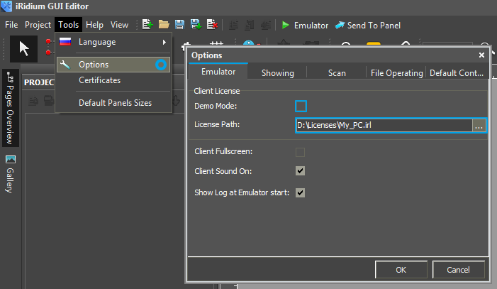
Operation modes for Emulator (see GUI Editor > Tools > Options > Emulator):
- Without the license (Demo Mode: on) – no connection with the controlled equipment.
- With the license (License Path: [...]) – when the license file is selected, all Emulator functions work and there is connection with the controlled equipment.
Indicate the path to the license file for Emulator (GUI Editor > Tools > Options > Emulator):
* When Demo Mode is activated Gui Editor won’t show the message about starting without the connection to the controlled equipment (without a license). Check if there is a license when setting up your project.
Emulator hot keys
- Click F5 to start Emulator.
- Click F8 to open the Emulator settings (password: 2007)
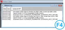
- Click F4 to open the Emulator log.
| For fully functional work of iRidium on your PC it is required to get an iRidium license and activate it for for your PC. Activation of licenses for iPad/iPhone/Mac/Android based or other devices does NOT lead to the automatic licensing of the PC with the installed iRidium Environment. A license for your PC is required for iRidium client on your PC (including Emulator) to work in the fully functional mode. The license should be purchased separately or you can use free For testing purposes you can use free licenses). |
Logging in Windows
iRidium Log is a window where information about iRidium work, error messages and iRidium Script logs (IR.Log) are output in the text format.
To open the iRidium log in Windows, click F4.
Launching Projects on Control Panels
Uploading and launching of iRidium projects on control panels are performed with the help of the iRidium Transfer application installed on your PC. You can also upload your project on the panel from GUI Editor with the help of Transfer.
- Instructions for setting up properties of the iRidium project launch on control panels: Properties for Launching iRidium Projects
- Instructions for uploading iRidium projects on control panels: iRidium Transfer.
- Instructions for setting up iRidium projects on control panel: iRidium App

